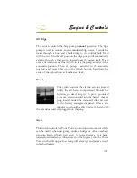

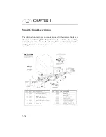


Systems
Systems
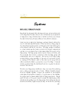
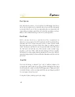
BILGE/DRAINAGE
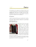
Regal boats are designed with a drainage system so water can be moved
to the bilge from the deck where it can exit hull side via a manifold. It
is important to keep all drains clear of debris so when a wave fl oods
the deck of the boat, all water will leave in an effective manner.
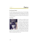
Select vessels use drains that discharge overboard directly without the
use of a hull side manifold system. Other vessels use a bilge pump in
the sump that can pump water out through a hole located along the
aft starboard hull side of your boat. The bilge pump is connected
to a fuse located near the battery switch in the engine compartment
and also to an automatic fl oat switch placed directly forward of the
bilge pump. The bilge pump receives power from your battery, and
the automatic fl oat switch is installed so that the bilge pump will
automatically turn on as required. The circuit to the bilge pump
receives battery power regardless of the state of your battery switch,
so turning off the battery switch at the end of each voyage will not
affect your boat’s ability to pump water out of the bilge. A manual
switch, operated from the dashboard however, requires the battery
switch to be activated.
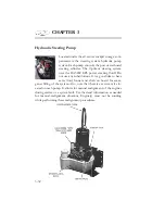
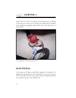
Monitor your bilge pump condition to keep your vessel from sinking
due to taking on large amounts of water. Debris should be cleared
from the impeller regularly. Inspect the condition of the impeller
and replace the impeller as necessary. To gain access to the impeller,
the pump must be disassembled from the bilge pump grate. Simply
push the tabs of the grate inward towards the bilge pump, while
simultaneously pulling up on the bilge pump. This locking mechanism
functions much like a quick disconnect clip. If the fuse for your bilge
Summary of Contents for 29 OBX
Page 1: ...OWNER S MANUAL OWNER S MANUAL 29 OBX 29 OBX REGAL 281760 REGAL 281760 3 2016...
Page 2: ...THIS PAGE IS LEFT INTENTIONALLY BLANK...
Page 7: ...INT 7 Introduction THIS PAGE IS LEFT INTENTIONALLY BLANK...
Page 18: ...INT 18...
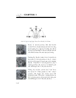
Page 38: ...u v u w CHAPTER 1 NAVIGATION LIGHT RULES...
Page 41: ...Safety On Board...
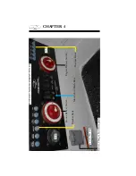
Page 94: ...Engine Controls 3 27 Typical Switch Shown Above...
Page 96: ...Engine Controls 3 29...
Page 162: ...Equipment Operation X Y Z Typical Dual Battery Switch Circuitry Front View...
Page 163: ...CHAPTER 6 _ Dual Battery Switch Circuitry Rear View...
Page 171: ...CHAPTER 6 CANVAS TRAVEL COVER...
Page 182: ...Equipment Operation Depth Gauge With Functions...
Page 196: ...Equipment Operation...
Page 257: ...Cosmetic Care Maintenance 7 35 Notes...
Page 262: ...Troubleshooting 8 5...
Page 263: ...CHAPTER 8 8 6...
Page 264: ...Troubleshooting 8 7...
Page 265: ...CHAPTER 8 8 8 0 1 0 2 3 4 5 6 2 4 6 7 8 9 2 3...
Page 273: ...CHAPTER 9 Notes...
Page 294: ...Technical Information 12 3 TYPICAL LABELS LOCATIONS Power Tower...
Page 299: ...Technical Information...
Page 305: ...Technical Information Note Locate per Splash...
Page 306: ...Technical Information...
Page 310: ...Technical Information TYPICAL HULL HARNESS BREAKOUT...
Page 311: ...Technical Information TYPICAL SWITCH PANEL BREAKOUT...
Page 312: ...Technical Information TYPICAL DASH CHARTPLOTTER BREAKOUT...
Page 313: ...Technical Information TYPICAL GARMIN YAMAHA NEMA 2000 NETWORK...
Page 324: ...Technical Information...


