


Equipment Operation
'
(
)
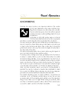
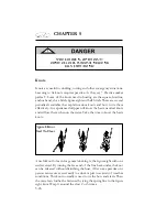
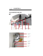
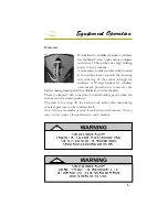
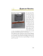
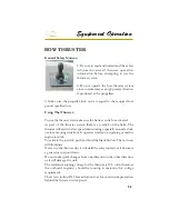
Paying Out Anchor Using Gravity
To let out the anchor release any anchor locks, insert the clutch handle
into the gipsy drive cap and turn it in a clockwise direction to tighten
the clutch. When in a safe mode, pull back on the clutch until the an-
chor and rode begin to pay out. Control the rate of anchor descent by
pushing the clutch lever forward. When the desired rode is paid out,
tighten the gipsy drive cap.
Paying Out Anchor Using Power
Make sure any anchor locks are disengaged and the pin through the
anchor shank is pulled along with the lanyard hook. Stand clear of all
windlass components when paying out.
Using the windlass momentary switch, press and hold the lower
portion of the switch. When the proper ratio of anchor rode is paid
out disengage the switch and tie off the rode to a cleat since it is not
recommended to let the windlass mechanism be the only source holding
the rode to the anchor on the sea bottom. Also, do not use the fail safe
pawl to hold the anchor load as windlass damage could occur.
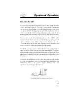
Hauling In Anchor- Manual Recovery
Insert clutch handle into the gipsy drive cap and turn clockwise until
anchor is fully returned to the bow roller.
Hauling In Anchor Using Power
When anchor rode is safe to haul in use the windlass momentary switch
to haul in the anchor rode. Press and hold the upper portion of the
switch until the anchor is returned to the bow roller position.
The fail safe pawl does not need to be disengaged during retrieval as it
will act as a ratchet. When the anchor has been retrieved in the bow
roller position the fail safe pawl should be left engaged in the gipsy to
prevent accidental activation of the windlass while underway.
Summary of Contents for 29 OBX
Page 1: ...OWNER S MANUAL OWNER S MANUAL 29 OBX 29 OBX REGAL 281760 REGAL 281760 3 2016...
Page 2: ...THIS PAGE IS LEFT INTENTIONALLY BLANK...
Page 7: ...INT 7 Introduction THIS PAGE IS LEFT INTENTIONALLY BLANK...
Page 18: ...INT 18...
Page 38: ...u v u w CHAPTER 1 NAVIGATION LIGHT RULES...
Page 41: ...Safety On Board...
Page 94: ...Engine Controls 3 27 Typical Switch Shown Above...
Page 96: ...Engine Controls 3 29...
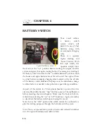
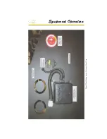
Page 162: ...Equipment Operation X Y Z Typical Dual Battery Switch Circuitry Front View...
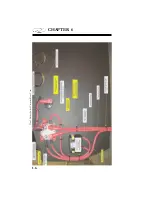
Page 163: ...CHAPTER 6 _ Dual Battery Switch Circuitry Rear View...
Page 171: ...CHAPTER 6 CANVAS TRAVEL COVER...
Page 182: ...Equipment Operation Depth Gauge With Functions...
Page 196: ...Equipment Operation...
Page 257: ...Cosmetic Care Maintenance 7 35 Notes...
Page 262: ...Troubleshooting 8 5...
Page 263: ...CHAPTER 8 8 6...
Page 264: ...Troubleshooting 8 7...
Page 265: ...CHAPTER 8 8 8 0 1 0 2 3 4 5 6 2 4 6 7 8 9 2 3...
Page 273: ...CHAPTER 9 Notes...
Page 294: ...Technical Information 12 3 TYPICAL LABELS LOCATIONS Power Tower...
Page 299: ...Technical Information...
Page 305: ...Technical Information Note Locate per Splash...
Page 306: ...Technical Information...
Page 310: ...Technical Information TYPICAL HULL HARNESS BREAKOUT...
Page 311: ...Technical Information TYPICAL SWITCH PANEL BREAKOUT...
Page 312: ...Technical Information TYPICAL DASH CHARTPLOTTER BREAKOUT...
Page 313: ...Technical Information TYPICAL GARMIN YAMAHA NEMA 2000 NETWORK...
Page 324: ...Technical Information...


