


CHAPTER 6
T
U
V
W
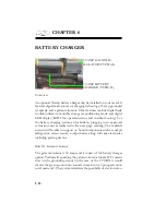
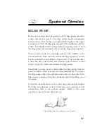
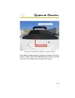
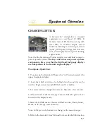
Your vessel utilizes
a
battery
switch
system
which
will
permit the use of dual
batteries along with
an automatic charging
relay.
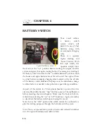
There is a separate
engine starting and
“house” battery. With
this style switch, the
operator simply turns
the knob to the “on” position before starting the engine and the
system energizes the engine starting battery. For emergency starting if
the battery switch is turned to the “combine batteries” position both
the house and engine batteries are activated to start the engine. There
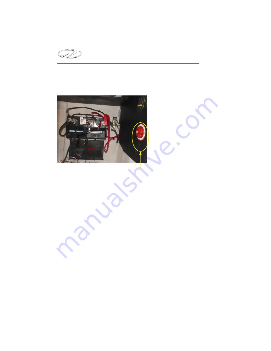
is a dual battery automatic charging relay located on the the aft side
of the battery switch bulkhead. Its purpose is the distribute a charge
to either battery as needed to keep them in a peak charge condition.
As part of this system is a 50 amp main breaker to protect the wire
circuitr
y. Should the breaker “trip” fi nd the source of the malfunction
before resetting the circuit breaker. Make sure the knob is fully de-
tented when selecting the “on” or “off ” functions. Again, remember
to deactivate the battery switch upon leaving the vessel.
Note that in the “ON” position the switch cranks the outboard en-
gine for starting purposes through the helm key switch system.
Note: There is an expanded battery switch system for dual outboard installations
verses the single outboard component addressed above.
Typical Dual Battery Switch
BATTERY SWITCH
Summary of Contents for 29 OBX
Page 1: ...OWNER S MANUAL OWNER S MANUAL 29 OBX 29 OBX REGAL 281760 REGAL 281760 3 2016...
Page 2: ...THIS PAGE IS LEFT INTENTIONALLY BLANK...
Page 7: ...INT 7 Introduction THIS PAGE IS LEFT INTENTIONALLY BLANK...
Page 18: ...INT 18...
Page 38: ...u v u w CHAPTER 1 NAVIGATION LIGHT RULES...
Page 41: ...Safety On Board...
Page 94: ...Engine Controls 3 27 Typical Switch Shown Above...
Page 96: ...Engine Controls 3 29...
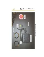
Page 162: ...Equipment Operation X Y Z Typical Dual Battery Switch Circuitry Front View...
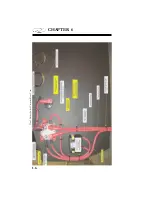
Page 163: ...CHAPTER 6 _ Dual Battery Switch Circuitry Rear View...
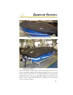
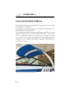
Page 171: ...CHAPTER 6 CANVAS TRAVEL COVER...
Page 182: ...Equipment Operation Depth Gauge With Functions...
Page 196: ...Equipment Operation...
Page 257: ...Cosmetic Care Maintenance 7 35 Notes...
Page 262: ...Troubleshooting 8 5...
Page 263: ...CHAPTER 8 8 6...
Page 264: ...Troubleshooting 8 7...
Page 265: ...CHAPTER 8 8 8 0 1 0 2 3 4 5 6 2 4 6 7 8 9 2 3...
Page 273: ...CHAPTER 9 Notes...
Page 294: ...Technical Information 12 3 TYPICAL LABELS LOCATIONS Power Tower...
Page 299: ...Technical Information...
Page 305: ...Technical Information Note Locate per Splash...
Page 306: ...Technical Information...
Page 310: ...Technical Information TYPICAL HULL HARNESS BREAKOUT...
Page 311: ...Technical Information TYPICAL SWITCH PANEL BREAKOUT...
Page 312: ...Technical Information TYPICAL DASH CHARTPLOTTER BREAKOUT...
Page 313: ...Technical Information TYPICAL GARMIN YAMAHA NEMA 2000 NETWORK...
Page 324: ...Technical Information...


