CHAPTER 4
Battery Switch(es)
All of your electrical systems onboard your Regal eventually connect
with your battery. This is where electrical power originates. In order
for any electrical system to receive power, with the exception of your
automatic bilge pump function and stereo memory requires a battery
switch(es) to be turned “ON”. The two excluded systems have a direct
battery feed at all times without the use of the battery switches. The
battery switches connect the battery to all deck and engine circuitry. It
is important to turn your batteries “ON” before each trip, and “OFF”
at the end of each cruise to avoid battery drain.
Never turn a battery switch to the “OFF” position when the outboard
engine is running as stator or other electrical system damage will occur.
Also, for extended non-use turn the battery switches to “OFF”.
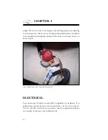
The standard battery switch is located below the stbd aft side seat
cushion. With the stereo performance package option normally a 40
amp breaker protects the amplifi er. A 60 amp breaker protects the
circuit wiring up to the helm.
The stereo memory and the bilge pump fuses are located near the
battery switch box as reference below. The stereo memory fuse is 15
amps and the bilge pump fuse and automatic side of the bilge pump
is 5 amps. These circuits will continue to function even with a battery
switch in the “OFF” position. It is recommended to turn all battery
switches to the “OFF” position when leaving the vessel for extended
periods. See the equipment chapter for further information.
Note that the above information utilizes a “house” battery switch and
an “engine” starting battery switch on your 29 OBX.
Summary of Contents for 29 OBX
Page 1: ...OWNER S MANUAL OWNER S MANUAL 29 OBX 29 OBX REGAL 281760 REGAL 281760 3 2016...
Page 2: ...THIS PAGE IS LEFT INTENTIONALLY BLANK...
Page 7: ...INT 7 Introduction THIS PAGE IS LEFT INTENTIONALLY BLANK...
Page 18: ...INT 18...
Page 38: ...u v u w CHAPTER 1 NAVIGATION LIGHT RULES...
Page 41: ...Safety On Board...
Page 94: ...Engine Controls 3 27 Typical Switch Shown Above...
Page 96: ...Engine Controls 3 29...
Page 162: ...Equipment Operation X Y Z Typical Dual Battery Switch Circuitry Front View...
Page 163: ...CHAPTER 6 _ Dual Battery Switch Circuitry Rear View...
Page 171: ...CHAPTER 6 CANVAS TRAVEL COVER...
Page 182: ...Equipment Operation Depth Gauge With Functions...
Page 196: ...Equipment Operation...
Page 257: ...Cosmetic Care Maintenance 7 35 Notes...
Page 262: ...Troubleshooting 8 5...
Page 263: ...CHAPTER 8 8 6...
Page 264: ...Troubleshooting 8 7...
Page 265: ...CHAPTER 8 8 8 0 1 0 2 3 4 5 6 2 4 6 7 8 9 2 3...
Page 273: ...CHAPTER 9 Notes...
Page 294: ...Technical Information 12 3 TYPICAL LABELS LOCATIONS Power Tower...
Page 299: ...Technical Information...
Page 305: ...Technical Information Note Locate per Splash...
Page 306: ...Technical Information...
Page 310: ...Technical Information TYPICAL HULL HARNESS BREAKOUT...
Page 311: ...Technical Information TYPICAL SWITCH PANEL BREAKOUT...
Page 312: ...Technical Information TYPICAL DASH CHARTPLOTTER BREAKOUT...
Page 313: ...Technical Information TYPICAL GARMIN YAMAHA NEMA 2000 NETWORK...
Page 324: ...Technical Information...

