5
h. Adjust Filter, regulator, lubricator (Frl)
Note: It is imperative the filter, regulator, lubricator be
employed when running the UPC Pneumatic. The air
should be clean, dry, and lubricated to maximize motor
life and performance.
1. Before pressurizing, fill the oiler with the oil provided, by
removing the large black cap on the top. (Do not exceed
the maximum fill line) Replace cap.
2. Set air pressure to 90 PSI maximum. Loosen wing-nut
on bottom of regulator, and turn large knob clockwise
until pressure is attained.
3. Turn the small set screw to set the oil drip. The oiler
should be set of 5-8 drops per minute.
i. Fill and Attach Water tank (not required for
cutting plastic pipe) to blade Guard
Water is used to help cool the diamond blades when cut-
ting cast iron, ductile iron and clay pipe. In cold tempera-
tures, low-level heat may be applied to the water tank,
or a non-toxic, environmentally safe, anti-freeze may be
added to the water.
iv. OPErAtiOn
A. Position the Cutting blade
1. Loosen blade guard locking knob until swing guard
rests on pipe.
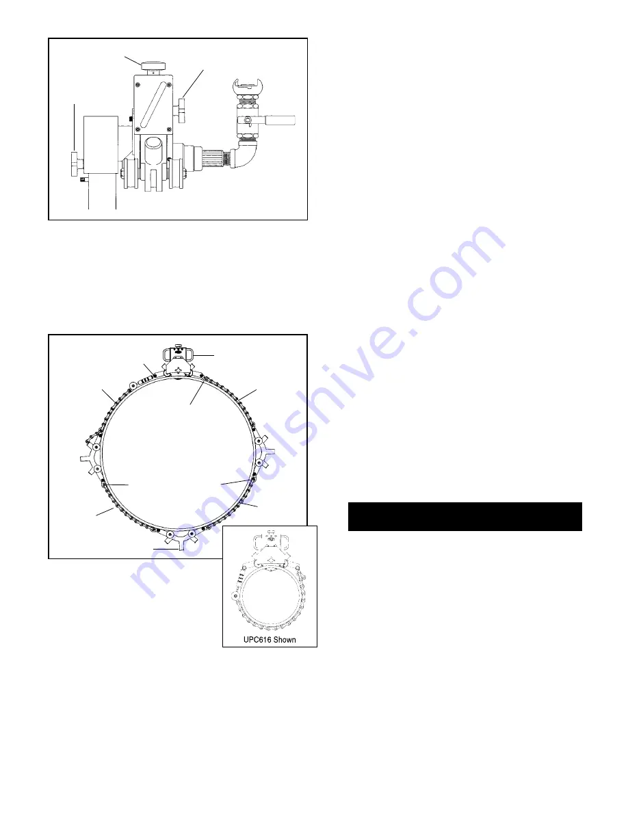
2. Turn cutter feed knob clockwise. (Fig.4) Lower motor and
cutter close to, but not touching the pipe. Motor bracket
locking knob should be tight, yet allow
the bracket to slide.
b. Pressurize Water tank by Following instructions
Provided with tank
Open valve on tank. Continue to repressurize tank dur-
ing use.
Special instructions
for cutting Steel Pipe and PE Pipe on next page.
C. turn Motor On
After ensuring air line is clear of dirt and debris, connect
air hose to motor. Open ball valve on motor.
WArninG: blade is now rotating, keep hands clear.
d. slowly Feed the blade into the Pipe.
Note: Fast feeding can result in tracking off.
1. Note position of depth gauge pointer (divided in tenths
of inches with MM references). (Photo #3)
2.* Knowing the thickness of pipe to be cut, turn the feed
knob clockwise, (Fig. 4) until the pointer indicates
the desired depth of cutter. Allow at least
1
/
4
" of blade
beyond depth of cut.
*Exception to this would be if the bevel cutter was being
used for plastic, then the cutter would be engaged until
the bevel cutter began cutting. At this point the depth
gage pointer could be used to determine amount of
bevel. Full engagement produces a
15
/
16
" bevel. (Fig. 4)
FIG. 5
F. Align Cutter (test tracking)
Rotate unit around pipe (one
revolution). To check tracking ac-
curacy, mark the pipe at one of the
motor unit rollers and rotate the
unit again and note off/on track condition. By tapping or
resetting the chain and/or connecting frames, the unit
can be aligned.
G. Connect Air supply
Unit is supplied with Street Ell, Ball valve and Dixon
coupling, however, any combination of piping to the unit
can be used as long as all fittings are full flow to ensure
maximum motor RPM. Always connect to warm air side
of compressor if so equipped. This will provide best tool
performance.
Connecting Frame
Motor Unit
release Pin
11 link
Chain
13 link
Chain
Chain hook (down)
Chain hook (Up)
UPC648
36" - 48" size shown
Motor bracket
locking Knob
Feed Knob
blade Guard
locking Knob
FIG. 4
6. If cutting pipe where connecting frames and 11 link
chains are needed, (UPC636 & UPC648) pre-assemble
chain hooks to the aluminum connecting frames, with
the chain hooks in the downward position. Return to
Step 5, being sure to space the connecting frames
equidistant to the motor unit. (Fig. 5)
11 link
Chain
11 link
Chain
Summary of Contents for UPC616A
Page 35: ...35...


