THE PVCore 3D PRINTER
12/28/2016
BY RCJOSEB
PAGE 51 OF 107
Y AXIS SLIDE ASSEMBLY:
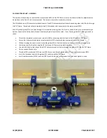
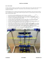
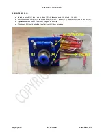
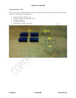
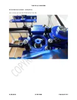
The picture above shows a partially completed Y slide body. It will not be completed until after the X axis is completed. During
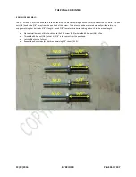
the assembly process, the #6 x 2.0” Phillips head screws (S2.0) will be used to hold the Y slide body parts together while the
bearing mount’s bolt (HB2.5) is inserted. This is done to ensure that the Y slide body does not put too much pressure on the 3D
printed linear bearing (LM6UU-3D). Too much pressure and the 6mm smooth rod (S6MM) will bind.
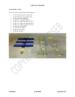
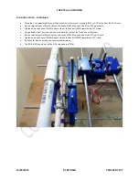
Marry the linear bearing (LM6UU-3D) to a smooth rod (S6MM) and label the smooth rod (S6MM) as Y left.
Keep the 3D printed linear bearing (LM6UU-3D) on the smooth rod (S6mm).
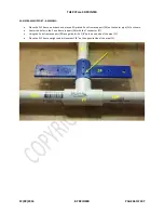
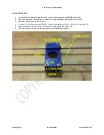
Place the 3D printed linear bearing LM6UU-3D between the upper and lower Y slides bodies (Y1) and (Y2).
Place one 3D printed Y slide block (Y3) on top of the Y slide body (Y2) while aligning the cutouts.
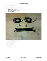
Thread a #6 flat washer (W6) onto a #6 x 2.0” Phillips pan head screw (S2.0) and insert into the block (Y3).
Thread a #6 washer (W6) and a #6 hex nut (N6) at the other end and hand tighten without Blue Loctite.
Repeat the above steps for the other side.
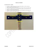
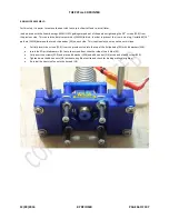
Thread the previously completed bearing mount onto the Y slide body while ensuring there are no binds.
Thread a 5/16” washer (W516) and a 5/16” hex nut (N516) onto the other end of the bearing mount bolt (HB2.5).
Use a small dab of Blue Loctite and tighten the 5/16” hex nut (N516).
Ensure that the linear bearings on the bearing mount and the 6mm smooth rod (S6MM) can move without binding.
Repeat the above steps to assembly the right Y slide.
Label it as Y right.


