THE PVCore 3D PRINTER
12/28/2016
BY RCJOSEB
PAGE 48 OF 107
Z AXIS - INSTALLATION:
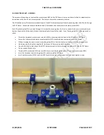
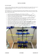
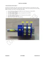
During the installation of the Z axis, do not tighten the hex nuts (N516) up against the Z axis top support (Z4) so that the entire Z
axis can be adjusted forwards and backwards. The placement of the Z axis will be determined when the X and Y axis
components are installed.
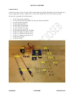
After assembling the Z axis, I encountered issues with the metal linear bearings (LM6UU-M), which are part of the Z axis slide
(Z2). I switched them out for the 3D printed ones (LM6UU-3D) and did not have to use the screws (S0.5) to hold them in place
because they were already a tight fit.
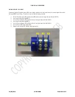
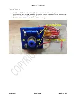
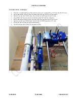
Insert the 6mm smooth rods (S6MM) into holes on the Z axis motor mount (M2).
Tighten down each #6 x 0.5” screw (S0.5) lightly so that it holds the smooth rod (S6MM) in place.
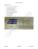
Insert the 14” x 5/16” threaded rod (T516) into the motor coupler (MC) but do not tighten the set screws.
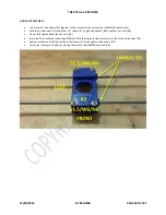
Thread the Z axis slide (Z2) onto the threaded rod (T516).
Ensure that the smooth rods (S6MM) engage the linear bearings (LM6UU-M or 3D) in the Z axis slide (Z2).
Lower the slide until it’s about two inches above the motor coupler (MC).
Insert the Z axis top frame support (Z3) onto the smooth rods (S6MM) and 5/16 threaded rods (T516) about 2”.
Partially insert the carriage bolts (B516) into the Z axis top support (Z3).
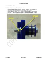
Thread a 5/16 washer (W516) and 5/16 hex nut (N516) in that order onto each bolt (B516) but do not tighten.
Thread a 5/16 hex nut (N516) and 5/16 washer (W516) in that order onto each bolt (B516) but do not tighten.
Continue threading the carriage bolts (B516) all the way into the Z axis top support (Z3) and into (Z4).
Thread a 5/16 washer (W516) and 5/16 hex nut (N516) in that order onto each bolt (B516) but do not tighten.
Insert a radial bearing (608ZZ) onto the threaded rod (T516) and Z axis top support (Z3).

