THE PVCore 3D PRINTER
12/28/2016
BY RCJOSEB
PAGE 38 OF 107
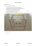
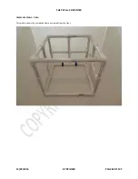
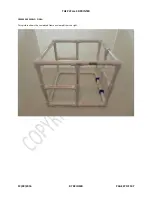
Z AXIS SLIDE ASSEMBLY:
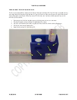
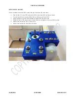
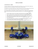
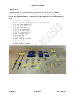
Please note that the following:
Attaching the two 0.25” x 12” threaded rods (T0.25) is OPTIONAL at this point as they will be removed later.
The hex nuts pictured to the left at the end of the threaded rod are threaded on without Blue Loctite.
The four #6 x 0.25” Phillips pan head screws (S0.25) are not inserted all the way, just left loose for now.
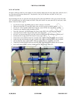
This picture shows the completed Z axis slide:
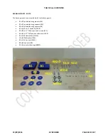
Apply a small amount of super glue to the outside of a 5/16 hex nut (N516).
Insert the 5/16 hex nut (N516) into the recessed hole at the top of the 3D printed Z axis slide (Z2).
Repeat the above steps for the other nut (N516) that gets insert at the bottom of the Z axis slide (Z2).
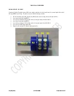
Insert a 0.25” x 12” threaded rod (T0.25) into one of the out holes in the 3D printed Z axis slide (Z2).
Leave 2” of the threaded rod (T0.25) protruding out of the 3D printed Z axis slide (Z2).
Insert a 5/16 washer (W516) and 5/16 nut (N516) on opposite sides of the Z axis slide (Z2).
Place a small amount of Blue Loctite on the threaded rod (T0.25) closest to the Z axis slide (Z2).
Tighten down the 5/16 hex nuts (N516) but do not overtighten or the Z axis slide (Z2) may crack.
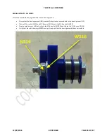
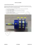
Thread four 5/16 hex nuts (N516) and 5/16 washers (W516) onto the threaded rod (T0.25) as shown.
Repeat the above steps for the other 0.25” x 12” threaded rod (T0.25).
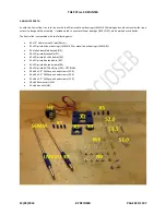
Insert four #6 x 0.5” Phillips pan head screws (S0.5) into the Z axis slide (Z2) as shown.

