THE PVCore 3D PRINTER
12/28/2016
BY RCJOSEB
PAGE 44 OF 107
Z AXIS MOTOR MOUNT - ASSEMBLY:
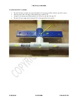
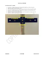
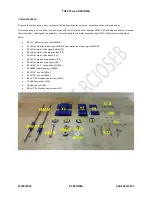
The purpose of these steps is to attach the motor mount (M2) to the PVC frame in a manner that will allow for adjustments to
be made once the X and Y axis are completed. This helps to ensure the maximum print area.
The 3D printed parts (Z1) that were installed as part of the PVC frame assembly will now be used as guides to drill holes through
the PVC frame. These holes will accommodate the 5/16 threaded rods connected to the motor mount (M2).
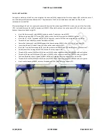
Each 3D printed guide (Z1) has a hole through it that should be running from the front to the back and are not centered top to
bottom. Examine the hole and verify that its bottom edge is closest to the table. If not, flip the guide (Z1) 180 degrees and re-
check.
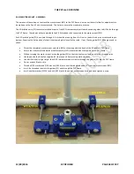
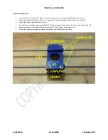
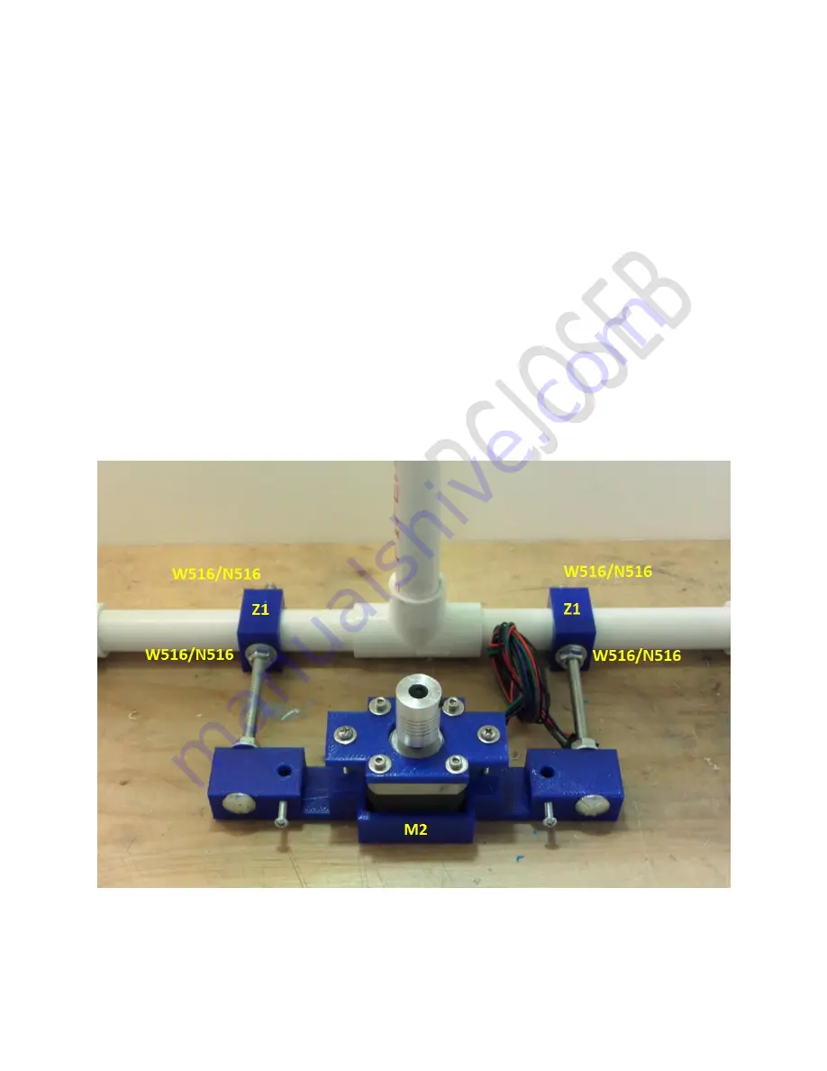
Orient the completed motor mount assembly (M2) as shown against the back of the 3D printer’s PVC frame.
Ensure that the completed motor mount assembly (M2) is centered when compared to the PVC frame.
Without moving the motor mount, move the guides (Z1) so that their holes are lined up with the threaded rods.
Use tape on both sides of each guide (Z1) to prevent it from moving while you drill.
Use a drill bit that is slight larger than 5/16 in diameter and drill holes through the guides (Z1) into the PVC frame.
Do not use any Blue Loctite.
Thread a 5/16 washer and 5/16 hex nut (N516) onto each threaded rod about 2” from the motor mount (M2).
Insert the threaded rods into the guides (Z1) and through the PVC frame.
Insert another washer (W516) and nut (N516) onto the end of each threaded rod and hand tighten loosely.

