


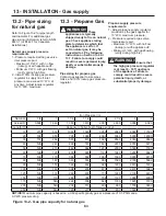

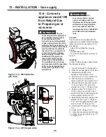


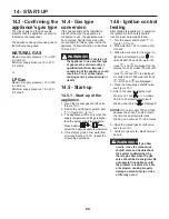


93
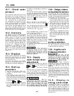
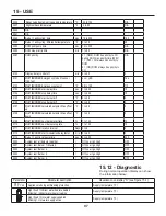
Figure 15-1 - Instrument panel and main power switch
T
020010.01.023
A - Key to reduce the supply water temperature;
B - Multifunctional key: reset any lockouts; access to user and installer menu.
C - Key to increase the supply water temperature;
D - Flame icon, is present when the flame is present;
E - Radiator icon. Present when appliance is enabled to work. Blinking when appliance working;
F - Faucet icon. Present when an indirect water heater (coil water heater) is enabled. Blinking when an indirect water heater (coil water
heater) is loading;
H - Unit of measure of the water system pressure
L - Burner unit indicators: Light when burner is burning; blinking when burner is in lockout or in blocking error
= Burner 1 (master)
= Burner 2
= Burner 3
= Burner 4
M - Water pressure gauge and indicator of the parameters
G - Icon indicating access to the installer menu
N - Supply water temperature gauge and indicator of the parameters value
O - Unit of measure of the temperature
P - Icon displayed when the outdoor sensor is active
Q - Flame crossed icon: is present when the appliance is in lockout or blocking error condition
R - Multifunctional key: scroll the parameters; increase the parameters’ value;
S - Multifunctional key: scroll the parameters; decrease the parameters’ value;
T - On-Off Main power switch
15 - USE
Summary of Contents for Infinite Energy2 IW1000
Page 3: ...3 SAFETY INSTRUCTIONS...
Page 5: ...5 SAFETY INSTRUCTIONS...
Page 122: ...122 16 MAINTENANCE...
Page 126: ...126 18 SPARE PARTS Spare parts...
Page 154: ...154 21 SEQUENCE OF OPERATION...


