


90
Figure 14-1 - Gas valve
D - Inlet gas pressure
probe
E - CO2 adjusting screw
F - Factory adjusted
regulator (Should never
be touched)
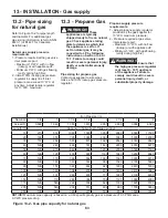
14.7 - Gas supply
pressure checking
WARNING!!!
DO NOT
adjust or attempt to measure
gas valve outlet pressure.
The
gas valve is factory-set for the
correct outlet pressure. This
setting is suitable for natural
gas and propane, requiring no
field adjustment. Attempting to
alter or measure the gas valve
outlet pressure could result
in damage to the gas valve,
causing excessive levels of
carbon monoxide, which can
cause severe personal injury or
death!
Check the gas supply pressure by
following the steps below:
1.- Close the manual gas shut-off
valve, Figure 13-1;
2.- Follow the steps in Section 16.2 to
remove the front cover;
3.- Turn the screw in pressure port “D”
shown in Figure 14-1 three turns
counterclockwise;
4.- Connect a manometer with
graduations of at least 0.1 in.W.C.
(0.25 mbar)
to the inlet gas port
“D” shown in Figure 14-1 (on unit
model 399 to 1000, choose the
pressure port “D” from any gas
valve present);
5.- Open the manual gas shut off
valve, Figure 13-1;
6.- Check that the gas supply
pressure does not exceed 13
in.W.C. If the gas supply pressure
is higher than 13 in.W.C. adjust the
upstream gas pressure regulator
to bring the gas supply pressure
between 12”WC and 13”WC;
7.- Turn the power switch to on
and generate a heat demand
by pressing button
to its
maximum setting. Also ensure that
the room thermostat is calling for
heat and operate downstream the
unit to verifiy the system is able to
dissipate all heat generated;
8.- Set parameter 2200 to “HIGH”
(see Section 15.11) (for appliance
model 199 use parameter 2010).
All burners will now start to run at
high fire;
14 - START-UP
E
D
F
E
D
F
020010.01.022
9.- Check the manometer to make
sure the gas supply pressure does
not drop below 3 in.W.C. (7.6
mbar). If the gas supply pressure
is lower than 3 in.W.C. means
that your inlet gas line or your gas
pressure regulator are not correctly
sized.
CAUTION!!!
Do not attempt
to adjust your upstream gas
pressure regulator. This
was already adjusted for the
maximum inlet gas pressure.
After verifying the correct gas
pressures:
1.- Back to set parameter 2200 to
“OFF” (on models 199 back to set
parameter 2010 to “OFF”). Now
appliance will back to work in
normal condition;
2.- Disconnect the manometer;
3.- Turn the screw in pressure
connection “D” in Figure 14-1,
clockwise until snug;
4.- Check pressure port “D” (Figure
14-1) for any gas leaks;
CAUTION!!!
Never force the
pressure connection screw or
the gas valve will be damaged!
WARNING!!!
Never use an
open flame to check for gas
leaks, a fire or an explosion
could result causing severe
personal injury or death!
5.- Close the manual gas shut-off
valve, Figure 13-1.
Summary of Contents for Infinite Energy2 IW1000
Page 3: ...3 SAFETY INSTRUCTIONS...
Page 5: ...5 SAFETY INSTRUCTIONS...
Page 122: ...122 16 MAINTENANCE...
Page 126: ...126 18 SPARE PARTS Spare parts...
Page 154: ...154 21 SEQUENCE OF OPERATION...


