


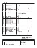
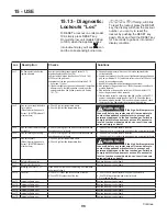


86
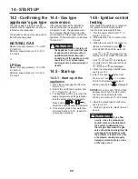
Figure 13-7 - Settings of the appliance for NATURAL GAS and LP GAS
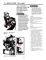
Figure 13-5 - Gas orifice
G
020010.01.019
E
D
F
E
D
F
020010.01.022
Figure 13-6 - Gas valve
U.M
199
399
500
750
1000
Orifice stamping for Natural gas
mm/100
No orifice No orifice
930
930
930
Orifice stamping for LP gas
mm/100
700
700
700
700
700
CO2 (Carbon dioxide) for Natural gas at high fire
%
8.4 to 8.7 8.4 to 8.7 8.8 to 9.1 8.8 to 9.1 8.8 to 9.1
CO2 (Carbon dioxide) for Natural gas at low fire
%
8.4 to 8.7 8.4 to 8.7 8.8 to 9.1 8.8 to 9.1 8.8 to 9.1
CO2 (Carbon dioxide) for LP gas at high fire
%
9.5 to 10
CO2 (Carbon dioxide) for LP gas at low fire
%
10.5 to 11.5
O2 (Oxygen) for Natural gas at high fire
%
5.9 to 5.4 5.9 to 5.4 5.2 to 4.7 5.2 to 4.7 5.2 to 4.7
O2 (Oxygen) for Natural gas at low fire
%
5.9 to 5.4 5.9 to 5.4 5.2 to 4.7 5.2 to 4.7 5.2 to 4.7
O2 (Oxygen) for LP gas at high fire
%
6.4 to 5.6
O2 (Oxygen) for LP gas at low fire
%
4.8 to 3.4
CO (Carbon monoxide) for Natural gas at high and low fire
ppm
Less than 150
CO (Carbon monoxide) for LP gas at high and low fire
ppm
Less than 250
WARNING!!!
Never use
an open flame to check for gas
leaks, a fire or an explosion
could result causing severe
personal injury or death!
13.- Turn the power on to the appliance;
14.- Turn completely counter clockwise
the screw “E” of Figure 13-6;
15.-
Checking gas supply pressure
following Section 14.7.
The minimum
gas supply pressure must not be
less than 3”WC (7.6 mbar) and the
maximum gas supply pressure must
not be higher than 13”WC (33 mbar);
16.- Verifying the CO2 rate and its
eventual adjustment following Section
13.8: The appliance during its normal
operation, within a maximum altitude
of 2,000 ft, has a CO2 exhaust rate
as shown in Figure 13-7. If not within
range of value shown, malfunctions
will occur;
WARNING!!!
The CO
(carbon monoxide) level should
not exceed values given in
Figure 13-7, when combustion is
correct. Failure to comply with
this requirement could result in
severe personal injury, death or
substantial property damage.
WARNING!!!
All
combustion measurements must
be performed with calibrated
equipment to ensure proper
reading and accuracy. Failure
to comply with this requirement
could result in severe personal
injury, death or substantial
property damage.
WARNING!!!
If the
combustion levels are not
within the range given in Figure
13-7 for the firing rate, shut the
appliance down and contact
your distributor or the appliance
manufacturer (see reference in
the last cover page). Failure to
comply with this requirement
could result in severe personal
injury, death or substantial
property damage.
17.- Check the capacity of the appliance
following Section 14.9;
18.- Attach to the front of the appliance
the appropriate conversion label,
found in the conversion kit (see
Figure 13-8 or Figure 13-9), stating
the new type of gas adjustment of the
appliance.
a - Apply the label in Figure 13-8 if
the appliance has been converted
to
LP GAS
;
b - Apply the label in Figure 13-9 if
the appliance has been converted
to
NATURAL GAS
.
13 - INSTALLATION - Gas supply
Summary of Contents for Infinite Energy2 IW1000
Page 3: ...3 SAFETY INSTRUCTIONS...
Page 5: ...5 SAFETY INSTRUCTIONS...
Page 122: ...122 16 MAINTENANCE...
Page 126: ...126 18 SPARE PARTS Spare parts...
Page 154: ...154 21 SEQUENCE OF OPERATION...


