OPERATION
NautoPilot 5000 Series
80
4002.DOC010102
Edition: September 2014
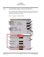
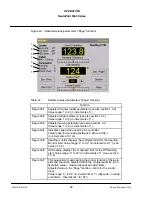
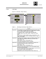
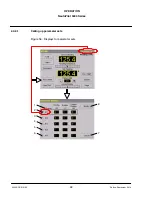
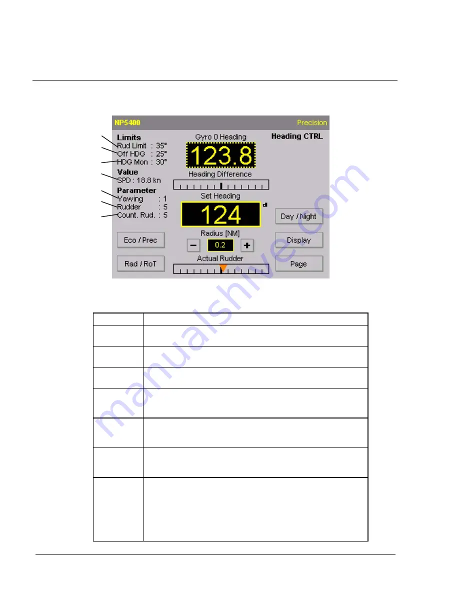
Figure 43: Indicated values/parameters (”Page” function)
1
2
3
4
5
6
7
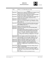
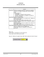
Table 12
Indicated values/parameters (”Page” function)
Function
Figure 43/1
Adjusted Counter rudder parameter (see also section 1.3.3).
Value range: 1 to 9 (in increments of 1).
Figure 43/2
Adjusted rudder parameter (see also section1.3.2).
Value range: 1 to 9 (in increments of 1).
Figure 43/3
Adjusted yawing parameter (see also section1.3.1).
Value range: 1 to 6 (in increments of 1).
Figure 43/4
Indicates speed value used by the controller.
Value range for manual adjustment: 5.0kn to 90.0kn,
(in increments of 0.1kn).
Figure 43/5
Heading monitor displays the configured limit for the Heading
Monitor alert. Value range: 5
to 30
(in increments of 1
) (see
section 1.3.5).
Figure 43/6
Off Heading displays the configured limit for the Off Heading
alert. Value range: 5
to 30
(in increments of 1
) (see section
1.3.6).
Figure 43/7
This adjustment is used during the control function of the Auto-
pilot and should be adjusted within the configured limits. (Con-
figuration value = maximum/physical rudder limits,
Adjusted value in the ”Page” function = limits for the control
loop).
Value range: 5
to 35
(in increments of 1
) (depends on config-
ured limits -- theoretical 5
to 180
).

