


D12585-2
0
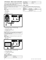
1. Check the selected location for the unit. A clear, flat area with
suitable clearance behind the panel is required.
2. Drill or knock out the 4 mounting holes on the unit
D12588-1
0
0
0
0
0
0
3. Fix the appropriate cutting template supplied with the product,
to the selected location, using masking or self-adhesive tape.
4. Using a suitable hole saw (the size is indicated on the
template), make a hole in each corner of the cut-out area.
5. Using a suitable saw, cut along the inside edge of the cut-out
line.
6. Ensure that the unit fits into the removed area and then file
around the rough edge until smooth.
7. Drill 4 holes as indicated on the template to accept the
securing screws.
8. Place the gasket onto the display unit and press firmly onto
the flange.
9. Connect the power, data and other cables to the unit.
10. Slide the unit into place and secure using the provided fixings.
Note:
The supplied gasket provides a seal between the unit
and a suitably flat and stiff mounting surface or binnacle.
The gasket should be used in all installations. It may also
be necessary to use a marine-grade sealant if the mounting
surface or binnacle is not entirely flat and stiff or has a rough
surface finish.
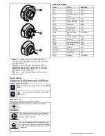
Bracket (trunnion) mounting
The display can be mounted on a trunnion bracket.
Before mounting the unit ensure that you have:
• Selected a suitable location.
• Identified the cable connections and route that the cables will
take.
• Attached the front bezel.
D12578-2
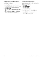
1. Mark the location of the mounting bracket screw holes on
the chosen mounting surface.
2. Drill holes for the screws using a suitable drill, ensuring there
is nothing behind the surface that may be damaged.
3. Use the fixings supplied with the mounting bracket to attach
securely.
4. Attach the display to the mounting bracket.
Front bezel
Attaching the front bezel
The following procedure assumes that the unit has already been
mounted in position.
1. Carefully lift one edge of the screen protection film, so that it
is accessible for removing when unit installation is complete.
2. Ensure the memory card slot door is in the open position.
3. Orientate the bottom-right side of the bezel under the lip of
the chart card door and place the bezel over the front of the
66
New a Series / New c Series / New e Series
Summary of Contents for a67
Page 2: ......
Page 4: ......
Page 8: ...8 New a Series New c Series New e Series...
Page 12: ...12 New a Series New c Series New e Series...
Page 20: ...20 New a Series New c Series New e Series...
Page 36: ...36 New a Series New c Series New e Series...
Page 70: ...70 New a Series New c Series New e Series...
Page 100: ...100 New a Series New c Series New e Series...
Page 110: ...110 New a Series New c Series New e Series...
Page 116: ...116 New a Series New c Series New e Series...
Page 158: ...158 New a Series New c Series New e Series...
Page 182: ...182 New a Series New c Series New e Series...
Page 204: ...204 New a Series New c Series New e Series...
Page 214: ...214 New a Series New c Series New e Series...
Page 236: ...236 New a Series New c Series New e Series...
Page 240: ...240 New a Series New c Series New e Series...
Page 260: ...260 New a Series New c Series New e Series...
Page 290: ...290 New a Series New c Series New e Series...
Page 306: ...306 New a Series New c Series New e Series...
Page 314: ...314 New a Series New c Series New e Series...
Page 329: ......
Page 330: ...www raymarine com...