


4.3 Power connection — New a Series
0
0
0
0
0
0
0
0
0
0
0
0
0
0
0
0
0
0
0
0
0
0
0
0
0
0
0
0
0
0
0
0
0
0
0
0
0
0
1
6
2
4
5
3
D12581-1
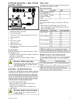
1.
Multifunction display rear panel connections.
2.
Power cable.
3.
Connection to 12 V power supply
4.
Red cable (positive).
5.
Shield (drain) wire (thin black wire; must be connected to
RF ground point).
6.
Black cable (negative).
Power distribution
Raymarine recommends that all power connections are made
via a distribution panel.
• All equipment must be powered from a breaker or switch, with
appropriate circuit protection.
• All equipment should be wired to individual breakers if
possible.
Warning: Product grounding
Before applying power to this product, ensure it has
been correctly grounded, in accordance with the
instructions in this guide.
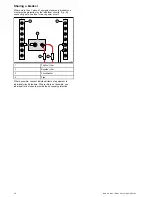
Grounding — Dedicated drain wire
The power cable supplied with this product includes a dedicated
shield (drain) wire for connection to a vessel's RF ground point.
It is important that an effective RF ground is connected to the
system. A single ground point should be used for all equipment.
The unit can be grounded by connecting the shield (drain) wire
of the power cable to the vessel's RF ground point. On vessels
without an RF ground system the shield (drain) wire should be
connected directly to the negative battery terminal.
The dc power system should be either:
• Negative grounded, with the negative battery terminal
connected to the vessel's ground.
•
Floating, with neither battery terminal connected to the
vessel's ground
Warning: Positive ground systems
Do not connect this unit to a system which has
positive grounding.
Power cable
The display is supplied with a power cable, this can be extended
if required.
Power cables available
For flush mount installations a right angled power cable (not
supplied) is available.
Cable
Part number
Notes
Right angled power
cable
A80221
Cable extension
The following restrictions apply to any extension to the power
cable:
• Cable must be of a suitable gauge for the circuit load.
• Each unit should have its own dedicated power cable wired
back to the distribution panel.
Total length (max)
Supply voltage
Cable gauge (AWG)
0–5 m (0–16.4 ft)
12 V
18
5–10 m (16.4–32.8 ft)
12 V
14
10–15 m (32.8–49.2 ft)
12 V
12
15–20 m (49.2–65.5 ft)
12 V
12
Note:
These distances are for a 2 wire power cable run from the
battery to the display (approximately the distance from the battery to the
display). To calculate the round trip length, double the figure stated here.
Breakers, fuses and circuit protection
It is recommended that you fit a thermal breaker or fuse at the
distribution panel.
Thermal breaker rating
5 A (if only connecting one device)
Note:
The suitable fuse rating for the thermal breaker is
dependent on the number of devices you are connecting. If in
doubt consult an authorized Raymarine dealer.
40
New a Series / New c Series / New e Series
Summary of Contents for a67
Page 2: ......
Page 4: ......
Page 8: ...8 New a Series New c Series New e Series...
Page 12: ...12 New a Series New c Series New e Series...
Page 20: ...20 New a Series New c Series New e Series...
Page 36: ...36 New a Series New c Series New e Series...
Page 70: ...70 New a Series New c Series New e Series...
Page 100: ...100 New a Series New c Series New e Series...
Page 110: ...110 New a Series New c Series New e Series...
Page 116: ...116 New a Series New c Series New e Series...
Page 158: ...158 New a Series New c Series New e Series...
Page 182: ...182 New a Series New c Series New e Series...
Page 204: ...204 New a Series New c Series New e Series...
Page 214: ...214 New a Series New c Series New e Series...
Page 236: ...236 New a Series New c Series New e Series...
Page 240: ...240 New a Series New c Series New e Series...
Page 260: ...260 New a Series New c Series New e Series...
Page 290: ...290 New a Series New c Series New e Series...
Page 306: ...306 New a Series New c Series New e Series...
Page 314: ...314 New a Series New c Series New e Series...
Page 329: ......
Page 330: ...www raymarine com...