Supplied By www.heating spares.co Tel. 0161 620 6677
25
5.13 ELECTRICAL
CONNECTIONS
5.13.1 IMPORTANT:
Electricity supply must be as
specifi ed in clause (sect. 4.10).
- When controls external to the appliance
are required, design of the external
electrical circuits should be undertaken by
a competent person In accordance with
the IEE wiring regulations. Factory fi tted
internal wiring must not be disturbed when
wiring external controls.
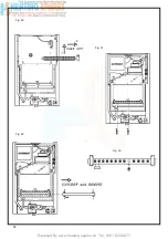
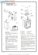
- To gain access to the electrical box
remove the front panel of the case as
described in clauses (sect.5.4.1) and the
instrument panel as described in clauses
(sect. 5 .4 .3).
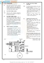
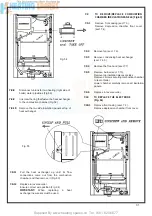
- The terminals are easily visible on the front
of the electronic control board (Fig. 48).
- Heat resistant fl exible cable is fi tted
between the isolator and the terminal block
A 3 core cable of 0.75 mm
2
(24x0.2 mm)
to BS 6500.
Make sure all wires to the appliance are
routed away from sharp edges and hot
surfaces .
The cable must be fastened with
its cord anchorage and connected so that
should the cable slip from the anchorage
the current carrying conductors become
taut before the earthing conductor .
Securely tighten all terminal screws and
arrange the cable with slack between the
cord anchorage and the terminal block.
WARNING:
If the supply cord is damaged,
it must be replaced by a service
engineer (supply cord available from
Ravenheat Manufacturing Ltd).
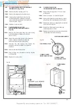
5.13.2
To gain access to the electrical connection
remove the front panel of the case as
described in clauses (sect. 5.4.1) .
Unscrew the 2 screws that fasten the
instrument panel .
Lift the instrument panel in order to detach it
from the sides, and lower it down by rotating
it on its own hinges .
The terminal box
is easily visible on the front of the control
panel Pull the electrical cover off to expose
connection (Fig. 48).
5.13.3
Heat resistant fl exible cable is fi tted between
the isolator and the terminal block. A 3 core
cable of 0.75 mm (24 x 0.2 mm) to BS6500
Make sure all wires to the appliance are
routed away from the sharp edges and
hot surfaces.The cable must be fastened
with its cord anchorage and connected so
that should the cable slip from the ancho-
rage the current carrying conductors be-
come taut before the earthing conductor.
Securely tighten all terminal screws and
arrange the cable with slack between the
cord anchorage and the terminal block.
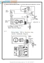
5.13.4
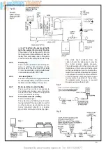
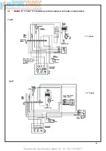
The pump must be connected directly to the
boiler terminal’s marked pump supply (Fig 94)
Any external controls must not interrupt
this electrical connection.
5.13.5
To fi t timer/programmer remove white link
wire ,
can be Free Volts or 230 Volts
(Fig.95 - 95.1 - 96 - 97).
5.13.6
Check the electrical installation for earth
continuity, short circuits, resistance to earth,
correct polarity and fuse failure.
WARNING:
if supply cord is damaged it
must be replaced by a service engineer
(supply cord available from Ravenheat
Manufecturing Ltd).
Summary of Contents for HE Primary AAA
Page 16: ...Supplied By www heating spares co Tel 0161 620 6677 17 Fig 18...
Page 31: ...Supplied By www heating spares co Tel 0161 620 6677 Fig 58 32 Fig 56 Fig 57...
Page 33: ...Supplied By www heating spares co Tel 0161 620 6677 34 Fig 60 Fig 61 Fig 62 Fig 63...
Page 42: ...Supplied By www heating spares co Tel 0161 620 6677 section 10 EXPLODED PARTS DIAGRAM 43...

