Supplied By www.heating spares.co Tel. 0161 620 6677
The system may be fi lled through a self
contained unit comprising of a cistern pres-
sure booster pump if required and if neces-
sary an automatic pressure reducing valve
or fl ow restrictor The cistern should be sup-
plied through a temporary connection from
a service pipe or cold water distributing
pipe The unit may remain permanently con-
nected to the heating system to provide lim-
ited automatic water make up
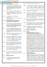
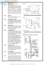
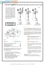
Mains topping up method (Fig 9)
Here the temporary connection is supplied
from a service pipe, or distributing pipe,
which also supplies other draw-off points at
a lower level
A combined double check valve shall be
installed upstream of the draw-off point,
through a temporary hose connection from
a tap supplied from the mains, where the
mains pressure is excessive a pressure
reducing valve shall be used to make fi lling
easier The following fi ttings shall form a
permanent part of the system and shall be
fi tted in the order stated
a) A stop valve complying with the require
ments of BS 1010 Part 2 (the temporary
hose from the draw off tap shall be con-
nected to this fi tting)
b) A test clock
c) Double check valve of an accepted
type
d) A non return valve of an accepted
type
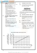
We recommend use of a Ravenheat
Filling Loop
designed for this
method
of
fi lling the system Available
from your supplier
PROVISIONS FOR MAKE UP WATER
(Fig 7)
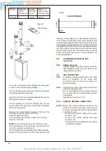
Provision can be made for replacing water
loss from the system either
A) from a manually fi lled made up bottle
with a readily visible water level The bottle
should be mounted at least 150 mm (6 in)
above the highest point of the system and
be connected through a non return valve
to the return side of the heating system
B) Where fi tting a make up vessel would
be diffi cult re pressurisation of the system
can be done See section on FILLING
If the capacity of the central heating system
14
Safety
valve setting (bar)
30
Vessel charge
pressure (bar)
05
10
15
Initial system
pressure (bar)
05
10
15
20
10
15
20
15
20
Total water
content of system
EXPANSION VESSEL VOLUME (LITRES)
Litres
25
50
75
100
125
150
175
200
225
250
275
300
325
350
375
400
425
450
475
500
21
42
63
83
104
125
146
1 6 7
1 8 7
2 0 8
2 2 9
250
2 7 0
2 9 1
31 2
333
3 5 4
375
396
41 6
35
70
105
140
175
210
245
280
31 5
350
385
420
455
490
525
560
595
630
665
7 0 0
65
129
194
259
324
388
453
51 8
583
647
71 2
7 7 7
841
906
97 1
1036
1101
1165
1230
1259
137
275
413
551
689
826
964
1102
1240
1377
151 5
1653
179 1
1928
2066
2204
2392
2479
261 7
2755
27
54
82
109
136
163
191
218
245
272
300
327
357
38 1
409
436
463
490
51 8
545
47
95
142
190
237
285
332
380
427
475
52.2
570
61 7
665
71 2
7 6 0
807
855
902
950
103
206
309
412
515
618
721
824
927
1030
1133
1236
1339
1442
1545
1648
1751
1854
1957
2060
39
78
117
156
195
234
27 3
312
35 1
390
429
468
507
546
585
624
663
702
741
7 8 0
83
165
248
331
413
496
579
662
745
827
910
993
1076
1158
1241
1324
1407
1489
1572
1 6 5 5
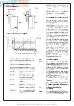
For system volumes
other than those given
above, multiply the
system volume by
the factor across
00833
0 140
0 259
0 551
0 109
0 190
0 412
0 156
0 331
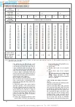
SIZING OF EXPANSION VESSEL TABLE 3
Note: This pressure can be increased up to 1.5 bar to suit high static head situations, see item 10, other appliance components in the
SERVICING INSTRUCTIONS
Summary of Contents for HE Primary AAA
Page 16: ...Supplied By www heating spares co Tel 0161 620 6677 17 Fig 18...
Page 31: ...Supplied By www heating spares co Tel 0161 620 6677 Fig 58 32 Fig 56 Fig 57...
Page 33: ...Supplied By www heating spares co Tel 0161 620 6677 34 Fig 60 Fig 61 Fig 62 Fig 63...
Page 42: ...Supplied By www heating spares co Tel 0161 620 6677 section 10 EXPLODED PARTS DIAGRAM 43...

