background image

Supplied By www.heating spares.co  Tel. 0161 620 6677


21

5.5.9 

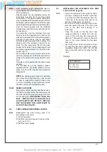
Each extension length extends the pipe by 
approximately 1000 mm long up to a maxi mum 
of two extensions.


Pipeline length can be established using the 
instructions in section 5.5 for rear fl ue  outlets 
and section 5.7 for side fl ue outlets. Extensions 
must be installed with the widened end of the air 
intake pipe and the tapered end of the fl ue pipe 
aimed towards the exhaust terminal. Extensions 
must be joined together with the standard 
terminal pipe, and inserted in each other as far 
as they can go.


If an extension must be shortened, this must 
be done from the straight end, and not from the 
widened or tapered end .To mea sure the pipeline 
properly all components must be assembled 
and total length mea sured before cutting. The 
straight end of the extension connects to the 
boiler. The fl ue output pipe fi ts into the boiler 
header until it stops .The air intake pipe should 
be located approximately 2 mm from the boiler 
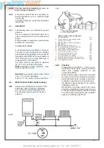
header (Fig 31).


When cutting both inner and outer ducts of the 
extension, always ensure that the reduced end 
(male) of the inner duct is longer than the outer 
duct.


All joints must be sealed with the rubber seals 
supplied.


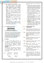
It is important to put the centering spacer, 
supplied with the unit, inside between the two 
pipes, from the side opposite the exten 

sion’s 

straight end. 


 NOTE: 

A

 suitable support bracket is availa ble 

from Ravenheat Manufacturing and should 
be used to support fl ue length at least every 
1.8 metre preferably at each joint this bracket 
should be secured to wall and fl ue duct.

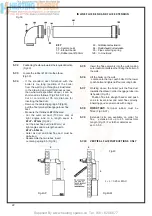
5.5.10 


INLINE FLUE BEND


Measure the distance between the fl ue bends or 
the fl ue/terminal assembly. The measurements 
should be taken from the outer edge of the fl ue 
and bend(Fig.39). 

IMPORTANT:


Inline  fl ue 

bend - 1680 mm must be deducted from 
overall length for each 90° bend -  1680 mm 
must be deducted from overall length for 
each 135° bend (Fig 39).

5.6 

COMPLETING BOILER INSTALLATION

5.6.1


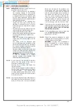
Reassemble the outer casing (sect 5 4) 


proceeding in this order 


1) Fit the two sides

2) Refi t the instrument panel in reverse ord er 
  as in  sect. 5.4.3.
3) Refi t the lower grating .

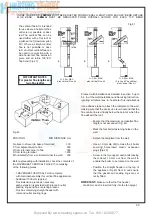
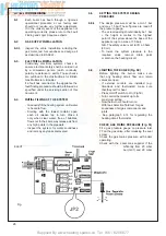
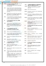
5.7.1  

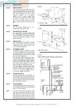
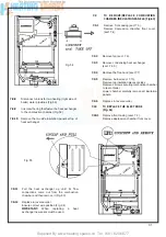
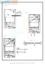
-  Attach the template to the wall with adhe- 
  sive tape, making sure that the centre line
  is vertical and that the distance from the
  centre line to the nearest side wall is not
  less than measurement in table 6.


-  Mark the four boiler securing holes on the
  wall and extend the axis of the fl ue  duct
  hole to the side wall ensuring it is 
 horizontal.


-  Trace the centre of the fl ue duct hole 
  measure distance F (table 6) From the
  corner of the wall (Fig. 28), measure the
  distance Y between the centre of fl ue duct
  hole to the corner Detach the template
 from 

wall. 

              -  Use a dia 10 mm drill to make the 4 holes 

  for securing the boiler Insert the plastic
  expansion plugs Core drill a 105 mm dia
  hole in the side wall for inserting the fl ue
 duct.

 TABLE 

6

CSI PRIMARY

F = 140 mm
G = 275 mm

5.7 

INSTALLING THE APPLIANCE FOR SIDE 
FLUE OUTLET (Fig. 28)

Summary of Contents for HE Primary AAA

Page 1: ...purposes only RAVENHEAT MANUFACTURING LTD CHARTISTS WAY MORLEY LEEDS LS27 9ET TEL 0044 0 113 252 7007 FAX 0044 0 113 238 0229 Website www ravenheat co uk E mail sales ravenheat co uk Instructions for...

Page 2: ...t exchanger constructed from copper Unique patented condensing heat exchanger for high thermal flue transfer gases to water Aesthetically pleasing panels and controls On Off ball valve for shutting of...

Page 3: ...TRICAL SYSTEM DIAGRAM EXPLODED PARTS DIAGRAM LIST OF SPARE PARTS PAGE 6 6 8 9 6 15 26 30 37 38 42 43 GENERAL LAYOUT Fig 1 KEY 1 Heat exchanger 3 Burner 4 Sensing electrode 6 Condensing heat exchanger...

Page 4: ...EME KEY 1 Heat exchanger 3 Burner 4 Sensing electrode 5 Flue restriction rin 6 Condensing heat exchanger 8 Condensing trap 9 Ignition electrode 18 Overheat cut off thermostat 22 C H sensor 26 Modulati...

Page 5: ...inlet duct 2 3 4 The boiler water temperature is automatically controlled by a built in thermostat 2 3 5 Interior space temperature is set by the room thermostat to be installed in the heating system...

Page 6: ...1 Siting of Ravenheat HE Primary Boiler must be as follows The position of installa tion should be within the building unless otherwise protected by suitable enclosure Adequate space for installation...

Page 7: ...in 2 0 mbar BURNER INJECTORS Nr 13 x 1 25 ELECTRICAL SUPPLY 230V 50 Hz POWER CONSUMPTION 60 W EXTERNAL FUSE RATING 3 A INTERNAL FUSE 2 A DRY WEIGHT 35 kg WATER CONTENT C H 0 5 litre GAS SUPPLY CONNECT...

Page 8: ...ar G 30 27 3 mbar min 7 3 mbar 7 0 mbar BURNER INJECTORS Nr 13 x 0 75 ELECTRICAL SUPPLY 230V 50 Hz POWER CONSUMPTION 60 W EXTERNAL FUSE RATING 3 A INTERNAL FUSE 2 A DRY WEIGHT 35 kg WATER CONTENT C H...

Page 9: ...above 6 inches 150 mm below 0 2 inches 5 mm on each side 1 inch 25 mm in front when installed in a cupboard 4 4 IMPORTANT NOTICE 4 4 1 If the boiler is to be fitted in a timber framed building it shou...

Page 10: ...bore and microbore central heating systems The following notes are given for general guidance 4 8 2 Pipework Copper tubing to BS 2871 1 1 1971 is reco mended for water pipes Jointing should be either...

Page 11: ...o BS4814 must be connected at a point close to the inlet side of the circulating pump see Fig 6E or as laid down by the manufacturer The expansion vessel must suit the volume of water in the system se...

Page 12: ...s could cause noise in the system or evene cause the safety thermostat to trip 4 8 4 Draining tap These must be located in accessible posi tions to permit the draining of the whole system The taps mus...

Page 13: ...visible water level The bottle should be mounted at least 150 mm 6 in above the highest point of the system and be connected through a non return valve to the return side of the heating system B Where...

Page 14: ...t exchanger Ravenheat recommended only the use of FERNOX COPAL SENTINEL X100 or SALAMANDER CURROSION GUARD water treatment products which must be used in accordance with the manufacturers instructions...

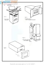
Page 15: ...carton containing Fig 15 a boiler fully assembled b installation instructions and user instructions c white paper template d terminal cover plate Polythene bag containing a 1 1 2 BSP Union Gas Cock b...

Page 16: ...Supplied By www heating spares co Tel 0161 620 6677 17 Fig 18...

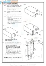
Page 17: ...ges Make sure the casing screws are put to one side in a safe place Fig 19 Fig 20 Fig 21 Fig 28 IMPORTANT Make sure that the elbow s dia 60 mm duct is inserted into the fan the rubber seal and orifice...

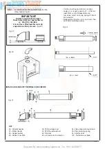
Page 18: ...ed Reassemble together inner and outer flue duct insert centering spring KEY 56 Straight header 57 Elbow header 58 Header gasket 59 Rubber seal 60 60 STD air intake duct 61 STD flue exhaust duct 62 Te...

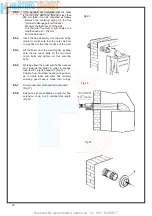
Page 19: ...header 57 Fig 31 Position flue into elbow header and push so as to locate inner and outer flue correctly ensuring good seal is made with o rings 5 5 7 Fit terminal cover plate and terminal guard Fig 3...

Page 20: ...bracket is available from Ravenheat Manufacturing and should be used to support flue length at least every 1 8 metre preferably at each joint this bracket should be secured to wall and flue duct 5 5...

Page 21: ...must be de burred Reassemble the two tubes insert centering spring 65 Fig 39 5 7 5 Insert the flue assembly into the wall making sure it will not interfere when fixing the boiler on the wall 5 7 6 Lif...

Page 22: ...mprising of the following pieces 1 RAVENHEAT VERTICAL FLUE complete with terminal assembly for vertical flue application Additional 1000 mm approx Flue Extension pieces as necessary each extension is...

Page 23: ...outer flue joint byinsertingthespigotendintothesocketendofthenext tube makingsurethesealringsarecorrectlylocated Fig 44 Make sure that the entire flue is adequately suppor ted Use at least one bracket...

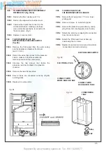
Page 24: ...m Ravenheat Manufacturing Ltd 5 13 2 To gain access to the electrical connection remove the front panel of the case as described in clauses sect 5 4 1 Unscrew the 2 screws that fasten the instrument p...

Page 25: ...h boiler operating Check with the Local Gas supplier if the pressure differs significantly from 20 mbar natural gas 37 mbar G31 and 29 mbar G30 SECTION 6 COMMISSIONING 6 1 Each boiler has been through...

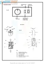
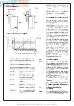
Page 26: ...pressure inlet 81 Downstream pressure outlet 104 Gas valve modulator 110 min regulator nut 111 Max regulator nut 114 Electrical connections modulator 115 Electrical connections Power Indicator On Off...

Page 27: ...ase pressure and anti clockwise to decrease pressure NOTE LPG ONLY The minimun pressure is factory set and sealed and cannot be adjusted 6 9 CHECKING THE FLUE SYSTEM 6 9 1 The flue system should be vi...

Page 28: ...ition lower left hand sub frame The following notes apply to the appliance anditscontrolsbutitshouldberemembered that attention must also be paid to the heating and hot water circuits with special att...

Page 29: ...sconnect the electrical connections from the fan motor 7 6 4 Support the fan and remove the two fixing screws and bracket from the front of the flue hood Carefully withdraw from condensing heat exchan...

Page 30: ...ve condensing heat exchanger sect 7 6 5 7 9 4 Remove the flue hood sect 7 7 Fig 54 Fig 55 7 9 TO REMOVE REPLACE COMBUSTION CHAMBER INSULATION PANELS Fig 63 7 9 1 Remove front casing sect 7 3 Remove de...

Page 31: ...Supplied By www heating spares co Tel 0161 620 6677 Fig 58 32 Fig 56 Fig 57...

Page 32: ...7 3 and remove the lower grating 7 16 2 Remove the 2 screws that fasten the instrument panel 7 16 3 Lower the instrument panel down by rotating it on its own hinges 7 16 4 Disconnect the electrical co...

Page 33: ...Supplied By www heating spares co Tel 0161 620 6677 34 Fig 60 Fig 61 Fig 62 Fig 63...

Page 34: ...ession chamber front cover sect 7 3 4 7 24 2 Detach the wires that connect to the pressure switch make sure that these wires are later reconnected to the same poles 7 24 3 Unscrew the two screws that...

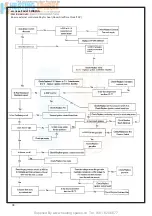
Page 35: ...Supplied By www heating spares co Tel 0161 620 6677 36 SECTION 8 FAULT FINDING Stat to maximum Ensure external controls calling for heat Room Stat Time Clock TRV...

Page 36: ...Supplied By www heating spares co Tel 0161 620 6677 Section 9 ELECTRICAL SYSTEM DIAGRAM Fig 94 37...

Page 37: ...Supplied By www heating spares co Tel 0161 620 6677 38 9 0 GENERAL SCHEMATIC DIAGRAM WIRING TO EXTERNAL SWITCHES AND THERMOSTATS VOLT FREE Fig 95 Fig 95 1...

Page 38: ...Supplied By www heating spares co Tel 0161 620 6677 9 1 WIRING TO Y AND S PLAN INSTALLATIONS USING AN EXTERNAL PROGRAMMER Y PLAN 39 S PLAN Fig 96 Fig 97...

Page 39: ...illustrated by drawings 10 air intake bend 90 10 flue exhaust bend 90 11 air inlet terminal 12 flue exhaust terminal 13 45 air intake bend duct 13 45 flue exhaust bend 14 flue exhaust duct 14 air inta...

Page 40: ...cone grease to ensure easy snug fit NOTE Exhaust flue must slope 2 down towards the boiler 35 mm fall per metre Spacing Clips Spacing clips are available on request should they be required NOTE for ec...

Page 41: ...he boiler 35 mm fall per metre IMPORTANT see Fig 6 and 42 for terminal clearances Exhaust suction system with two separate pipes throu gh a single vertical wall Maximum distance D I E Totale exhaust i...

Page 42: ...Supplied By www heating spares co Tel 0161 620 6677 section 10 EXPLODED PARTS DIAGRAM 43...

Page 43: ...11 0008VAL09015 0 Dungs gas valve 12 0005PRE06006 0 Air Pressure Switch 13 0001DIA06005 0 E23 730 Flue restriction ring 79 HE F2 14 0014TUB01006 1 Red Nylon tube from pressure switch 15 0007TER08010 0...

Page 44: ...x 2 gas valve 34 5018025 372851 Gasket 18 5 x 11 6 x 2 35 5018030 372867 Gasket 24 x 15 x 2 36 0019CUR06005 1 Elbow header 37 0019PR005005 0 Flue extension duct complete 38 0019TER06005 1 Flue duct an...

Page 45: ...Telephone 0044 0 113 252 7007 Tfax 0044 0 113 238 0229 Website www ravenheat co uk E mail sales ravenheat co uk Ravenheat reserves the right to make changes and improvements in our products which may...

Page 46: ...FOR ALL BOILERS YES NO YES NO CONTROLS To comply with the Building Regulations each section must have a tick in one or other of the boxes REQUIREMENT MEASURES PROVIDED 1 TIME AND TEMPERATURE CONTROL...

Page 47: ...DATE ENGINEER NAME COMPANY NAME TEL No CORGI ID SERIAL No COMMENTS SIGNATURE SERVICE 4 DATE ENGINEER NAME COMPANY NAME TEL No CORGI ID SERIAL No COMMENTS SIGNATURE SERVICE 2 DATE ENGINEER NAME COMPAN...

Reviews: