Supplied By www.heating spares.co Tel. 0161 620 6677
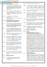
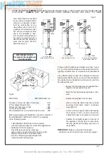
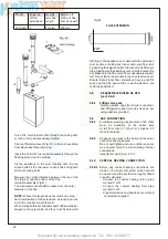
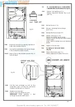
Fig 37
20
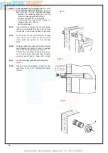
5.5.4
Insert the fl ue assembly into the wall, being
careful to make sure that the outer air duct
comes fl ush to the inner surface of the wall.
5.5.5
Lift the boiler on to the wall (Fig 34), locating
onto the top coach bolts Fit the two lower
coach bolts and tighten all four securing
bolts.
5.5.6
Working above the boiler pull the fl ue exhaust
duct towards the boiler in order to engage
tube item 61 into its header 57 ( Fig.31).
Position
fl ue into elbow header and push so
as to locate inner and outer fl ue correctly
ensuring good seal is made with o-rings.
5.5.7
Fit terminal cover plate and terminal guard.
(Fig.37)
5.5.8
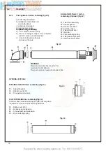
Extension kits are available on order for fl ue
extension of up to 2.5 metres total length
(Fig.31).
Fig 36
Fig.35
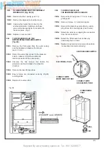
5.5.3
If the standard duct furnished with the boiler
is too long (the wall to go through is less than
680 mm thick) it can be shortened as follows
- Remove the centering spring 65, the fl ue
terminal to disengage inner fl ue duct
- Measure the thickness W of the wall
- Cut the outer fl ue duct at right angles to a
length equal to W + 152 mm
Must be de-burred.
Summary of Contents for HE Primary AAA
Page 16: ...Supplied By www heating spares co Tel 0161 620 6677 17 Fig 18...
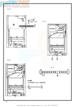
Page 31: ...Supplied By www heating spares co Tel 0161 620 6677 Fig 58 32 Fig 56 Fig 57...
Page 33: ...Supplied By www heating spares co Tel 0161 620 6677 34 Fig 60 Fig 61 Fig 62 Fig 63...
Page 42: ...Supplied By www heating spares co Tel 0161 620 6677 section 10 EXPLODED PARTS DIAGRAM 43...

