Supplied By www.heating spares.co Tel. 0161 620 6677
35
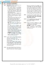
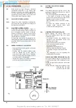
7.25 TO
REMOVE/REPLACE
THE IGNITION/CONTROL BOARD
7.25.1
Remove front casing (sect. 7.3 and lower
gratin panel.
7.25.2
Remove 2 screw to instrument panel.
7.25.3
Remove the plastic box protection by unclip
ping it from its 4 locating pins (2 each side).
7.25.4
Detach the wires by unclipping the connectors
from the control board.
7.25.5
Detach the PCB board from its base by
unscrewing the 4 screws.
7.25.6
Replace in reverse order( ensure all electrical
connections are made correctly).
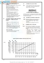
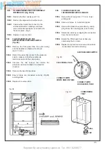
7.24
TO REMOVE/REPLACE THE
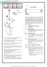
DIFFERENTIAL PRESSURE SWITCH
(Fig.
65)
7.24.1
Remove the front panel from the outer casing
and the depression chamber front cover
(sect. 7.3 & 4).
7.24.2
Detach the wires that connect to the pressure
switch, make sure that these wires are
later reconnected to the same poles.
7.24.3
Unscrew the two screws that fasten the
pressure switch to the back of combustion
chamber.
7.24.4
Remove the two silicone tubes.
7.24.5
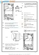
Ensure tubes are connected correctly (Fig.65)
avoiding
kinks.
7.24.6
Replace in reverse order.
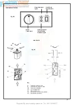
7.22
TO REMOVE/REPLACE THE OVERHEAT
THERMOSTAT (Fig. 78,79)
7.22.1
Remove the front casing (sect. 7.3)
7.22.2
Remove the depression chamber cover.
7.22.3
Unscrew the 2 wires that connect to the
overheat termostat, macking sure these
wires will subsequently be reconnected to
the same poles. (Fig.1).
7.22.4
Replace in reverse order .
AIR PRESSURE SWITCH
CONDENSING
TRAP
SEAL
CAP
ELECTRICAL PLUG
CONNECT WITH
RED SILICON TUBE
Fig. 66
Fig. 65
CONNECT WITH
WHITE SILICON TUBE
Fig. 64
Summary of Contents for HE Primary AAA
Page 16: ...Supplied By www heating spares co Tel 0161 620 6677 17 Fig 18...
Page 31: ...Supplied By www heating spares co Tel 0161 620 6677 Fig 58 32 Fig 56 Fig 57...
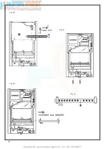
Page 33: ...Supplied By www heating spares co Tel 0161 620 6677 34 Fig 60 Fig 61 Fig 62 Fig 63...
Page 42: ...Supplied By www heating spares co Tel 0161 620 6677 section 10 EXPLODED PARTS DIAGRAM 43...

