Supplied By www.heating spares.co Tel. 0161 620 6677
13
The sta
tic head available from the
cistern should be adequate to provide
the initial system design pressure.
The cold feed pipe from the cistern should
include a non-return valve, and a stop-valve
with an automatic air vent connected be -
tween them, with the stop valve being locat-
ed, between the cistern and the automatic
air vent The stop valve may remain open
during normal operation of the system,
if automatic water make-up is required
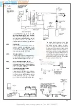
Booster pump method (Fig 8).
controls
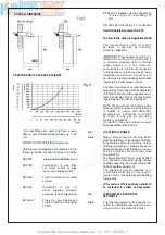
Therefore a by-pass must be fi t-
ted to the system (15 mm min) (Fig. 6A).
If the volume of circulating water is too low,
the boiler water temperature will rise too
rapidly This could cause noise in the system
or evene cause the safety thermostat to trip
4.8.4. Draining
tap
These must be located in accessible posi-
tions to permit the draining of the
whole system The taps must be at least
15 mm nominal size and manufactured
in accor dance with BS 2870 1980.
4.8.5 Air
release points
These must be fi tted at all high points where
air will naturally collect, and must be sited to
facilitate complete fi tting of the system.
4.8.7 Mains
water
feed: central heating
There must be no direct connection to
the mains water supply, even through a
non- return valve, without the approval
of the Local Water Authority.
4.8.8
Permissible methods of fi lling
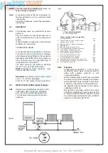
Cistern method (Fig 8)
The system may be fi lled by one of the fol-
lowing methods Through a cistern used for
no other purpose, via a ballvalve perma-
nently connected directly to a service
pipe and/or cold water distributing pipe .
Summary of Contents for HE Primary AAA
Page 16: ...Supplied By www heating spares co Tel 0161 620 6677 17 Fig 18...
Page 31: ...Supplied By www heating spares co Tel 0161 620 6677 Fig 58 32 Fig 56 Fig 57...
Page 33: ...Supplied By www heating spares co Tel 0161 620 6677 34 Fig 60 Fig 61 Fig 62 Fig 63...
Page 42: ...Supplied By www heating spares co Tel 0161 620 6677 section 10 EXPLODED PARTS DIAGRAM 43...

