background image

30 


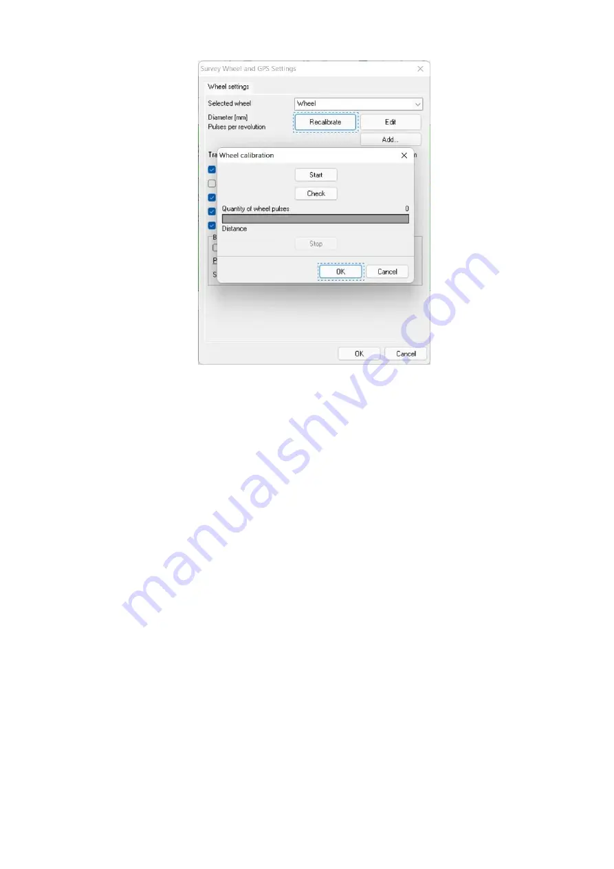
Fig.8.4. Survey wheel calibration 


Software uses the captured wheel pulses to understand is wheel rotating or not. 
If  wheel  is  not  moving  the  traces  are  not  adding  to  the  acquiring  profile.  The 
calculated traveled distance is recording to the header of each acquiring  profile 
trace.  

o


Automatic  real  time  data  X-interpolation

  –  equidistant


traces  acquisition, 

when each trace has the preliminary defined trace spacing (dX) to each other. 

o


Trace  spacing  [dX]

  –  is  used  to  adjust  the  resolution  along  the  profile.  This 

value depends  on the minimum  size of the detected object, taking into account 
the fact that it is desirable to have 3-5 traces crossing the object. Those if the size 
of  the  object  is  15  cm,  then  the  dX  should  be  5  cm,  but  preferably  1  cm.  But 
note,  that  too  small  dX  leads  to  traces  and  the  acquired  profile  increasing.  The 
dX can be specified both in the wheel settings window and before the each start 
of  data  acquisition.  This  is  controlled  by  the 

Ask  about  trace  spacing  before 

acquisition

 item. 

o


Bidirectional wheel

 – detection of toward/backward wheel direction.  

o


Reverse  wheel direction

 –  wheel  direction changing  while bidirectional wheel 

is used, i.e. backward movement becomes to forward movement and vice versa. 
This is may be used for different ways to move the GPR antenna (drag after the 
operator or push it in front of him), especially for a shock-proof cart. 

o


Replace  existing  trace  data  on  backward  movement

  –  while  the  antenna 

moves  forward,  the  profile  is  displayed  on  the  screen  from  left  to  right,  but  if 
antenna moves back, then the profile also builds back, i.e. from right to left with 
a  white  vertical  marker  in  front.  If  the  antenna  moves  back  along  exactly  the 
same  path,  then  it  looks  like  a  white  vertical  marker  moving  back  along  the 
profile. This feature of the wheel is very useful for pinpointing of underground 
utilities;  the  vertical  white  marker  aligns  exactly  with  the  top  of  the  hyperbola 

Summary of Contents for Prism 2

Page 1: ...Version 2 7x User s Manual Riga 2022...

Page 2: ...ing 42 11 Profile handling 44 12 Multi profiles operations 57 12 1 Profiles combining wizard 57 12 2 Profiles splitting wizard 58 12 3 Profiles 3D alignment wizard 59 13 Profiles post processing 61 14...

Page 3: ...processing and its interpretation Note computer has to be equipped with LAN 10 100 BaseT or Gigabit device to operate the Zond Python and or zGPR family of georadars by Ethernet cable or with WiFi dev...

Page 4: ...mplified block diagram of GPR The transmitter excites the transmitting antenna with very short electrical pulses The transmitting antenna radiates ultra wideband one and half period electromagnetic wa...

Page 5: ...the overall dynamic range of the entire system There have been various methods for digitizing analog signals since the advent of digital technologies One of the main methods used in pulsed georadars...

Page 6: ...The limitation of this method is the frequency of transmitter triggering which affects both the stroboscopic converter and the number of received traces per second which is relatively small at the le...

Page 7: ...cantly changes the general structure of the pulsed GPR First of all this is the refusing from the analog stroboscopic converter because its functions are now performed by an ultra fast field programma...

Page 8: ...point should be set to the middle of the transmitter pulse lobe direct wave The way to set the zero point is described in Section 11 Working with sounding data files on page 46 This is a very importan...

Page 9: ...ny in phase axes The reasons of the noise appearing are irregular electromagnetic processes in the GPR equipment itself and external electromagnetic fields of natural and artificial origin for example...

Page 10: ...ig 4 1 Trace output Fig 4 2 Wiggle plot profile output black and white and colored one Fig 4 3 Line scan output grayscale and colored one Note The most informative output method is the line scan in th...

Page 11: ...ipped by a built in wireless router that automatically configures the TCP IP settings of user s PC TCP IP settings have to be set to Obtain an IP address automatically For Zond 12e Single Channel Zond...

Page 12: ...10 Press OK button 11 Press Close button 12 Close the Network and Sharing Center window For Windows 8 10 11 1 Right click on bottom left corner on your Desktop and then press Control Panel 2 Chose the...

Page 13: ...Double click the Network connections icon 3 Double click your wireless Wi Fi connection icon and then click the Properties button 4 Select Internet protocol TCP IP and click the Properties button 5 F...

Page 14: ...automatically in the feature 14 If you are using factory default Wi Fi access point settings then follow to the next point otherwise chose the security method for Wi Fi connection end enter pass code...

Page 15: ...setting it up link like it shown on the figure below Fig 5 1 Wi Fi network Set up dialog We recommend using Maximum Performance power option for the wireless Wi Fi connections to avoid problems with...

Page 16: ...15 Fig 5 2 Power options dialog Fig 5 3 Edit power options dialog...

Page 17: ...umber 0537 Python 3 from the serial number 0027 and zGPR family units contain internal wireless router with complex operation system You need to contact with our customer support before you try to cha...

Page 18: ...fault one by pressing OK button The next step is to enter the Radar Positioning menu item or the Connections Positioning brief menu item and select one from the four possible positioning methods for t...

Page 19: ...ng this item you can select the required file and display it on the screen by typing its name in the File name line or select the required file from the list and load it by clicking the Open button If...

Page 20: ...ent profile data amplitude values to the text ASCII file txt as a Tab separated table where each traces filled as a rows and samples as columns Raw data raw data not gained not filtered export Process...

Page 21: ...to split selected profile s to the several profiles see on p 58 Profiles 3D aligning aligning of parallel profiles acquired for 3D imaging in third party software see on p 59 Print Profile printout i...

Page 22: ...rogram o Windows tabs show hide the profiles tabs for the quick profiles access in the lower part of the application main window o Show status bar show hide the Status bar in the lower part of the app...

Page 23: ...ilter digital frequency filtering of signals If a Customized High Pass Filter was used during sounding then the lower right column of the profile is active o Frequency filter filter parameters adjustm...

Page 24: ...outputs the amplitude of the traces on the specified sample along the visible profile see p 51 o Cut traces and samples deleting undesirable traces and samples from the profile see p 51 o Hodograph so...

Page 25: ...om 0 to 255 Inserted mark s number is applying automatically and is not sequential It s better to Rebuild marks at the end of its insertion or deleting process to rearrange its indexes sequentially o...

Page 26: ...cordance to the stored GPS coordinates for active profile distance rebuilding of the current active profile for all opened profiles distance rebuilding of all opened profiles Note basic spherical elli...

Page 27: ...tomatic detection of connection interface for communication with Cobra GPR o Ethernet connection for communication with Cobra Wi Fi GPR or Cobra CBD GPR o Bluetooth connection for communication with C...

Page 28: ...6 Window profile windows positioning Tile vertical vertical windows positioning Tile horizontal horizontal windows positioning Tile smart windows positioning in consideration of the profiles size Cas...

Page 29: ...files on page 50 Wheel survey wheel method of positioning It is possible to use different types of measuring wheels for example our current measuring wheel has a diameter of 200 mm a shock proof cart...

Page 30: ...the GPR and get an access to the wheel data captured by the GPR for the wheel calibration First of all place the GPR antenna with the connected wheel at the starting point of the calibrating path Setu...

Page 31: ...he wheel settings window and before the each start of data acquisition This is controlled by the Ask about trace spacing before acquisition item o Bidirectional wheel detection of toward backward whee...

Page 32: ...the COM port list of the Bluetooth wheel GPS global positioning system or GNSS global navigation satellite system it combines signals from different satellite navigation systems as GPS USA GLONAS Russ...

Page 33: ...Local Positioning and Quality that contains positioning in Mercator and its accuracy it provides coordinates in the UTM coordinates reference system o Distance calculation during GPS positioning depen...

Page 34: ...y be distorted on non equidistant profiles Wheel GPS combined Wheel and GPS positioning option where the coordinates are recorded in the trace header but the traveled distance is measured by the wheel...

Page 35: ...ing Do not connect or disconnect cables while GPR is powered 9 2 Power up PC and GPR If you use wireless connection please make sure that PC is connected to the GPR wireless network Zond 12e Python Co...

Page 36: ...Distance the traveled distance of the current profile Positioning selected positioning type Battery GPR battery level Ping the connection quality results on the base of the ICMP ping request the measu...

Page 37: ...36 Python 3 GPR settings interface shown on Fig 9 2c zGPR settings interface shown on Fig 9 2d Fig 9 1a Single channel GPR settings Fig 9 1ba Double channel GPR settings...

Page 38: ...a working position for example at the beginning of the possible sounding path Controls navigation is possible with the help of keys and selection Enter or Spacebar or touchable if such possibility is...

Page 39: ...s and thousands of times but without averaging only summation that enlarge the data sample length from the initial 16 bits to 32 bits zGPR signal to noise ratio and its penetration depth are increasin...

Page 40: ...ed only single channel mode when Tx antenna connected to channel 2 and Rx antenna connected to channel 1 o Circle mode for Zond 12e Advanced only modes are changing continuously in row Channel 1 Chann...

Page 41: ...antenna architecture The following high pass filters are available for different types of the GPR o Zond 12e GPR family there are different hardware filters states OFF Weak Strong and Super Strong Pl...

Page 42: ...e its first lobe is the center of the first green oscillogram grid cell Software stores Pulse Delay adjustment for each Antenna Range combination and there is no need to adjust it always Positioning t...

Page 43: ...If the Radar When to save During the acquisition option is enabled the software asks to specify the filename for the future profile before sounding if menu Radar Sounds is checked user here Let s go...

Page 44: ...ose the data acquisition mode with the acquired data on the screen software replaces it as a separate profile window with name Profile 1 in the main view for post processing and prompt to save it on i...

Page 45: ...ways The number of profiles to be displayed in the screen shall be unlimited By default they will be arranged in a cascaded pattern you may also choose their layout patterns at your discretion in opti...

Page 46: ...changed The result of your actions will be immediately displayed on the profile If you need multi vertex gain function you can add new vertexes up to 10 For this purpose press the button and click on...

Page 47: ...offset the simple time depth recalculation contains the error This error depends on offset and measured depth ratio because simple recalculation doesn t consider direct wave propagation time between t...

Page 48: ...such as pipes cables stones archeological objects areas of drastic soil properties variation their signals on the radiolocation profiles have hyperbola shape signal examples are shown in Figs 4 2 4 3...

Page 49: ...l disappear Zoom in selected area magnification To select magnification area press and hold the left mouse button and select required zooming area After releasing mouse button selected area will exten...

Page 50: ...is when choosing bandwidth and suppression frequencies filters Ormsby bandpass and Notch filter Fig 11 6 Spectrum Output dialog box in different amplitude scale units in times in dB There are differen...

Page 51: ...at the desired place vertical line with a crosshair will appear on the profile indicating trace position You can also navigate along the profile by pressing or keys Fig 11 8 Trace inspection window B...

Page 52: ...vertically for samples Dialog window will appear after the mouse button releasing allowing you to correct initial and final trace or sample ranges for cutting out Cutting could be applied to the curre...

Page 53: ...ows working with annotation objects moving text moving line vertexes deleting objects and changing their properties To move the objects or vertexes select them by pointing your cursor under the object...

Page 54: ...t the program will offer the same filename as initial profile name with txt extension Fig 11 12 Lines Settings dialog box o Area Used to distinguish layers of the profile with different geophysical me...

Page 55: ...es between media along the profile from the maxima of the reflected signals with an option to save the defined interface as an ASCII file After selecting this option dialog window will appear letting...

Page 56: ...ted to the right of the color palette You may select the required color by clicking rectangle button located to the right of the square button The pop up dialog box will offer you to choose a color fr...

Page 57: ...s identified with unsupported coordinate system its data will be interpreted as Degrees Minutes Export export coordinate table s data into ASCII text file txt in accordance to selected coordinate syst...

Page 58: ...the hard drive Fig 12 1 Profiles combining wizard dialog box on the 1st step User can add profiles from the hard drive pressing button Add on the 1st step Profiles could be added one by one or severa...

Page 59: ...box Make folder Fig 12 2 Profiles combining wizard dialog box on the 2nd step The button Next pressing starts the process of profiles combining please wait while software process the selected profiles...

Page 60: ...rofiles using the its marks from mark to mark The resulting files names and location are managed in the same way like in the combining wizard see on p 57 12 3 Profiles 3D alignment wizard Profiles whi...

Page 61: ...test one of the set Fill up initial profiles are filling by zero traces trace where each sample equal to zero up to the longest one of the set The resulting files names and location are managed in the...

Page 62: ...satisfied with processing results or if you would like to change procedure parameters you can undo processing results selecting Processing Undo processing or by pressing button If you would like to re...

Page 63: ...lter acting along a trace Designed for low frequency interference and signal s high frequency components suppression The algorithm used here comprises three steps application of direct FFT fast Fourie...

Page 64: ...nd trace becomes next to last and so on This may be useful when any area is sounded by tacks i e the first profile is covered and then the second is made with an offset and in the opposite direction a...

Page 65: ...ed together in the average trace Stacking contributes to suppression of noise and interference and to increase of the depth rating However it should be remembered that stacking decreases the trace amo...

Page 66: ...anging Migration reconstruction of original shape of underground interface and local objects by its radiolocation profile Very effective when having diffracting objects underground utilities fixtures...

Page 67: ...e in Windows Procedures execution sequence goes from top to bottom Moving any procedure to the left will make it active and allow you to change its parameters when selecting left mouse click on the ac...

Page 68: ...nion black and white color scale is the most informative line scan profile displaying type see Example in Fig 4 3 left side It would provide clear visibility of the weak signals Always pay attention t...

Page 69: ...n PICOseconds 3220 2 short int Number of samples per trace for this reel s data 3222 2 Unused 3224 2 short int Data sample format code 1 32 bit IBM floating point 2 32 bit fixed point integer 3 16 bit...

Page 70: ...hin CDP ensemble 28 2 short int Trace identification code 1 seismic data 2 dead 3 dummy 4 time break 5 uphole 6 sweep 7 timing 8 water break 9 optional use 30 2 short int Number of vertically summed t...

Page 71: ...d recording start in PICOseconds 110 4 Unused 114 2 short int Number of samples in this trace 116 2 short int Sample interval of this reel s data in PICOseconds 118 42 Unused 160 2 short int Hour of d...

Page 72: ...ny point thereof in reality this is not always the rule as the most media are layered One of the best known methods used for layer by layer velocities determination is Common Depth Point method CDP or...

Page 73: ...cm one acquired trace one step 11 The total Hodograph distance has to be 2 times greater than measuring depth 12 The Hodograph profile distance has to be entered to profiles settings as Length of pro...

Page 74: ...t 1 m is set for all layers This is quite sufficient for most cases Adjustment shall be made only in cases where the software fails to find a solution 5 Now enter the air wave position which is fully...

Page 75: ...face 8 Everything is ready for the calculation now Press Calculate button If the data is correct the software calculates this may take a few seconds and outputs the result Calculated signal paths will...

Page 76: ...sent IP address of As default it is 192 168 0 10 4 Click the Unit settings button The Zond 12e Ethernet settings dialog box appears Note Please use the Connection troubleshooter if the error message a...

Page 77: ...1 The Control Unit with IP address is unreachable Possible reasons What to do 1 Entered IP address is not correct Reenter IP address and try again your action 2 Computer is not configured Configure yo...

Page 78: ...our local network administrator If you want to change the security mode of Wi Fi access point please use following steps 1 Run any internet browser all examples are based on Internet Explorer 10 here...

Page 79: ...w trendnet com asp download_manager inc_downloading asp iFile 17937 Starting from 2015 in Zond 12e serial numbers from 0537 GPR contains internal network router that is able to automatically configure...

Page 80: ...n number of samples and traces To equalize profiles do please follow the menu File Profiles 3D aligning 2 The Voxler window consists of three separate areas Network Properties and visualization You ca...

Page 81: ...to be sure that all Geometry Limits of the imported data module are set properly to see it just left mouse click on the module and follow to the Properties area of Voxler window Geometry tab The X ax...

Page 82: ...nches by drag n drop mouse action 9 Please try to play with different graphic outputs to understand how it works and visualize the imported data The best graphic output method of 3D cube is Isosurface...

Page 83: ...file and chose Run as administrator Application starts minimized creating tray icon User needs to configure it first to be able to use it There are two different configurations the first one is the Co...

Page 84: ...rted and configured the Prism2 Right click on the PrismClicker tray icon and chose Connection setup of its menu Fig C3 PrismClicker tray menu You have to choose the connection protocol serial COM port...

Page 85: ...in Prism2 Commands list The Set button has to be pressed after choosing the commands User is able to left click the necessary place of the third party software what is needed to be simulated after Pre...

Page 86: ...operating Prism2 and remote operating PrismClicker computers take a look on the part 5 2 for computers configuration of this manual for details if you are going to use manual TCP IP configuration rem...

Page 87: ...iting your feedback with great pleasure If you found any difficulty using our equipment do not hesitate to contact us or our representatives by phone e mail or mail We cherish sincere hopes that the e...

Reviews: