Oil circuit
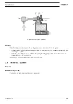
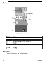
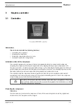
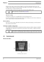
Flow diagram, oil circuit
Description
In air receiver/oil separator (AR), most of the oil is removed from the air/oil mixture by centrifugal action.
The remaining oil is removed by oil separator (OS). The oil collects in the lower part of air receiver/oil
separator (AR), which serves as an oil tank.
The oil system is provided with a thermostatic bypass valve (BV). When the oil temperature is below its set
point, bypass valve (BV) shuts off the supply to oil cooler (Co) and the oil cooler is bypassed.
Air pressure forces the oil from air receiver/oil separator (AR) through oil filter (OF) and oil stop valve (Vs)
to compressor element (E).
Bypass valve (BV) starts opening the supply from cooler (Co) when the oil temperature has increased to the
set point. At approx. 15 ˚C (27 ˚F) above the set point, all the oil flows through the oil cooler.
Oil stop valve (Vs) prevents the compressor element from flooding with oil when the compressor is stopped.
The valve is opened by element outlet pressure when the compressor is started.
Instruction book
2920 7101 21
13
Summary of Contents for QGS 40
Page 1: ...QGS 40 QGS 50 QGS 60 QGS 75 QGS 100 Instruction book Oil flooded rotary screw compressors...
Page 2: ......
Page 100: ......
Page 101: ......


