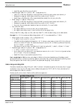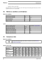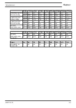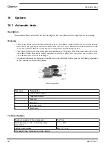
• Install the prescribed fuse on each cable
• Parallel supply cable (2 x 3 PE - configuration (2)):
• Add 10 % to the total compressor current (I
tot
Pack or I
tot
FF from the tables) and divide by 2
• Multiply the ampacity of the cables with 0.8 (see table A.52.17 (52-E1))
• Install fuses of half the size of the recommended maximum fuse size on each cable.
• When using 2 x 3 PE as in (3):
• Add 10 % to the total compressor current (I
tot
Pack or I
tot
FF from the tables) and divide by √3
• Multiply the ampacity of the cables with 0.8 (see table A.52.17 (52-E1))
• Fuse size: the recommended maximum fuse size divided by √3 on each cable.
• Size of the PE cable:
• For supply cables up to 35 mm²: same size as supply cables
• For supply cables larger than 35 mm²: half the size of the supply wires
Always check the voltage drop over the cable (less than 5 % of the nominal voltage is recommended).
Example:
I
tot
= 89 A, maximum ambient temperature is 45 °C, recommended fuse = 100 A
• Single supply cables (3 PE - configuration (1)):
• I = 89 A + 10 % = 89 x 1.1 = 97.9 A
• The table for B2 and ambient temperature = 45 ° C allows a maximum current of 93 A for a 50 mm²
cable. For a cable of 70 mm², the maximum allowed current is 118 A, which is sufficient. Therefore,
use a 3 x 70 mm² + 35 mm² cable.
If method C is used, 50 mm² is suffficient. (35 mm² for method F) => cable 3 x 50 mm² + 25 mm².
• Parallel supply cable (2 x 3 PE - configuration (2)):
• I = (89 A + 10 %)/2 = (89 x 1.1)/2 = 49 A
• For a cable of 25 mm², B2 at 45 °C, the maximum current is 63 A x 0.8 = 50.4 A. So 2 parallel cables
of 3 x 25 mm² + 25 mm² are sufficient.
• Install 50 A fuses on each cable instead of 100 A.
Fuse calculations for IEC
are done according to 60364-4-43 electrical installations of buildings, part 4:
protection for safety- section 43: protection against overcurrent. Fuse sizes are calculated in order to protect
the cable against short circuit. Fuse type aM is recommended but gG/gL is also allowed.
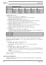
Cable sizing according CSA
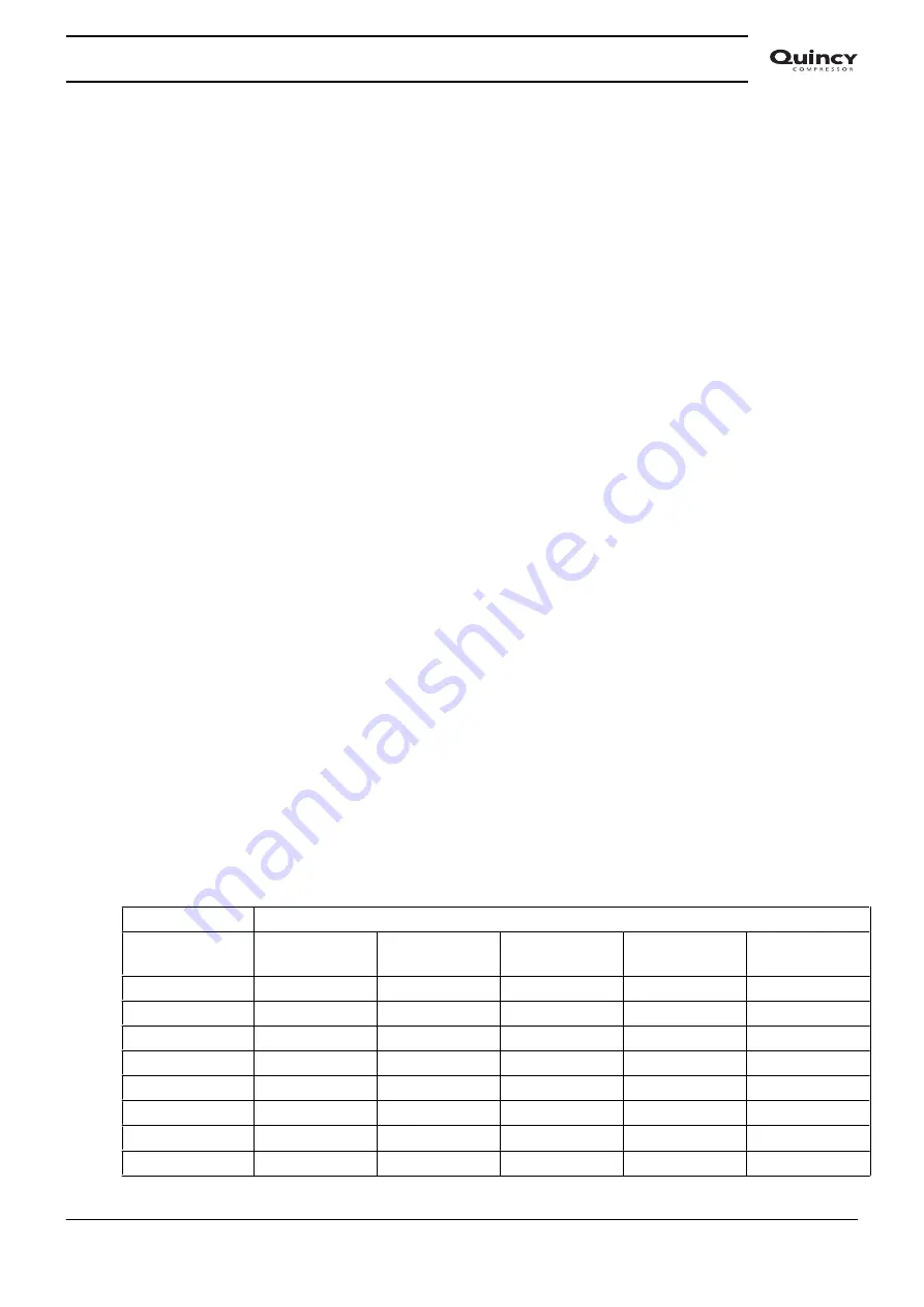
Calculation method according CEC part 1, table 2 column 3: allowable ampacities for not more than 3 copper
conductors in raceway or cable (based on an ambient temperature of 30 °C (86 °F). Correction factors for
other temperatures table 5A column 3.
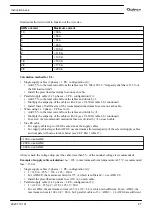
Maximum allowed current in function of the ambient temperature
Ambient temperature
Cable section
(AWG or kcmil)
30 °C (86 °F)
40 °C (104 °F)
45 °C (113 °F)
50 °C (122 °F)
55 °C (131 °F)
10
< 30 A
< 26 A
< 25 A
< 23 A
< 20 A
8
< 45 A
< 40 A
< 37 A
< 34 A
< 29 A
6
< 65 A
< 57 A
< 53 A
< 49 A
< 42 A
4
< 85 A
< 75 A
< 70 A
< 64 A
< 55 A
3
< 100 A
< 88 A
< 82 A
< 75 A
< 65 A
2
< 115 A
< 101 A
< 94 A
< 86 A
< 75 A
1
< 130 A
< 114 A
< 107 A
< 98A
< 85 A
1/0
< 150 A
< 132 A
< 123 A
< 113 A
< 98 A
Instruction book
2920 7101 21
85
Summary of Contents for QGS 40
Page 1: ...QGS 40 QGS 50 QGS 60 QGS 75 QGS 100 Instruction book Oil flooded rotary screw compressors...
Page 2: ......
Page 100: ......
Page 101: ......

