BAUER
BAUER
COMPRESSORS
Instruction Manual and Replacement Parts List
BAUER Compressors, Inc.
Phone: (757) 855-6006
1328 Azalea Garden Road
Fax: (757) 855-6224
Norfolk, Virginia 23502-1944
www.bauercomp.com
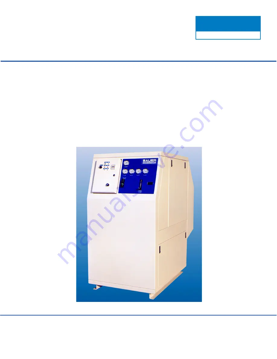
MAXI VERTICUS
High Pressure Breathing Air Compressor
MVT26
October 2003
MNL- 0345


