Configuration Page
511000 Rev. F
age
to be
ayed on the screen. Note that
the Configuration Screen displays what resources are possible, not what is currently
ges
e Save button is pressed. Pressing the
Cancel button will remove all of the current editing and revert to the last saved
version of the partition page.
9.3
Configuration/Partition Items P
The Configuration/Partition Items page allows for logical library partition items
assigned simply by selecting the available elements displ
installed. The elements may be viewed by either their physical addresses or which
partition they are currently assigned to by touching the view button. Each of the
possible partitions may be viewed by touching the partition button. Note that chan
to these screens will not be saved until th
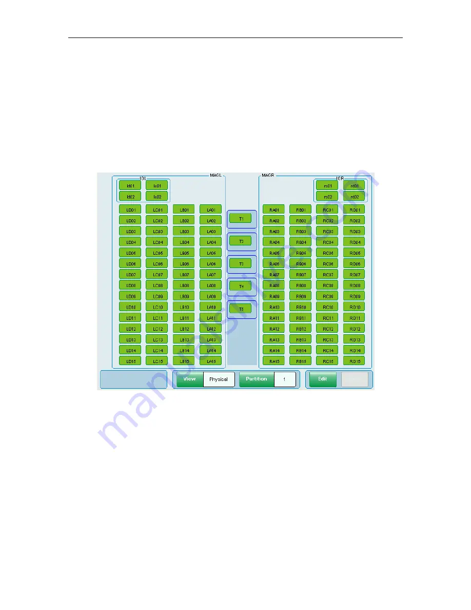
Partition Configuration Screen
Figure 9-16
Figure 9-16 shows a library with five tape drives (T1 – T5) with left and right storage
matrices (MAGL and MAGR). The left and right I/O ports are represented by IOL and
IOR. Note that the Handler (H) is not shown because it is a shared resource that
cannot be dedicated to any particular partition.
Elements assigned to the partition currently being viewed are displayed in green,
elements reserved for a different partition will be gray and unassigned elements will
be white. Yellow elements represent the output slots assigned in a partition
containing a tape drive operating in Dual Bin sequential mode. Touching an element
not assigned to the current partition will toggle it to being assigned to the current
partition. Touching it again will toggle it back to its previous assignment.
9-18


