background image

88

 1001108-01-F

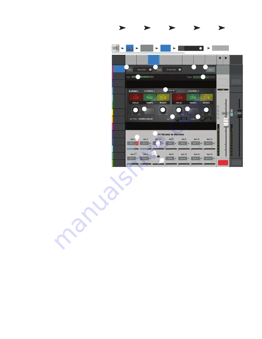
FX Processor – Mono and Stereo Delay

These effects delay the audio signal to create echo and 
similar effects. Controls for the stereo delay may be 
linked or operated independently. 

Input channels and Sub Groups are able to send to 
the effect.

1. 

Effect

 – Touch to select a different Effect Type.

2. 

Preset –

 Displays the name of the current 

preset. Touch to access the preset library.

3. 


4. 

Reset –

 Returns processor and Aux Send 

controls to their default settings.

5. 

Input –

 Displays the incoming audio level 

before the Effect.

6. 

Output –

 Displays the post-effect audio 

level.

7. 

Link Button –


(Stereo Delay only)


– Links all controls of both channels. Channel 
two is set to the same level as Channel one.

8. 

Delay Knob

 – Sets the delay time in 

milliseconds.

9. 

Tap Tempo Button

 – Sets the tempo 

of the regenerations by tapping. Touch the Tap 
Tempo button, then tap the Master Control knob 
at a steady rate. 

10. 

Regen Knob

 – Adjusts the amount of 

delayed signal that is sent back to the input. At 0% only the first echo will be heard. At 99% the echo will repeat indefinitely at the 
same level.

11. 

Lo Cut Knob

 – Attenuates, or “cuts” frequencies below this frequency setting. Range is 20 Hz to 2 kHz. 

12. 

Hi Cut Knob

 – Attenuates, or “cuts” frequencies above this frequency setting. Range is 200 Hz to 20 kHz.

13. 

FX Returns to Monitors

 – Sliders adjust the level of the effect heard in the performers’ monitors.

a. 

M –

 Indicates the Aux Send for the Effect is muted from the Auxes tab. 

b.  Send Slider – Sets the level of the Effect to the Aux output.

c.  Link icon – Indicates the Auxes are linked.

d.  Aux Pan control – Pans between the two linked Auxes.

Home

Touch the 

FX Masters 

Bank

Touch an 

FX Channel

Touch the 
Effect Tab

Touch Effect 

Pull-Down

Touch Stereo 

or Mono 

Delay


Joe’s Monitor

Aux 1

Aux 2

Aux 2

Aux 3

Aux 3

Aux 4

Aux 4

Aux 5

Aux 5

Aux 6

Aux 6

Aux 7

Aux 7

Aux 8

Aux 8

Aux 9

Aux 9

Aux 10

Aux 10

Aux 11

Aux 11

Aux 12

Aux 12

Aux 13

Aux 13

Aux 14

Aux 14

Overview

E

ffect

Auxes

Setup

EQ

Presets

Default

Scene:

Main Mix

L/R

Prev

Next

L

G

48

L

F

LR

1

2

3

4

5

6

7

8

Cue

L

C

R

Mic

1

10

5

u

5

10

20

0

40

10

10

5

u

5

10

20

0

40

10

In 1

Main

Cue

Main

L/R

Mute

Mute

Tap

Tempo

Tap

Tempo

Inputs 1-8

FX 1

Effect

FX Masters

Stereo or Mono

Delay

Effect

None

+

2

4

5

1

10

9

7

8

11

6

12

3

9

8

10

13

a

b

c

d

Summary of Contents for touchmix-30 pro

Page 1: ...1001108 01 F 1001108 01 TouchMix User Manual TouchMix 30 Pro Firmware Version 2 0 TouchMix 16 Firmware Version 3 0 TouchMix 8 Firmware Version 3 0...

Page 2: ...t registers stoves or other apparatus including amplifiers that produce heat 12 To reduce the risk of electrical shock the power cord shall be connected to a mains socket outlet with a protective eart...

Page 3: ...energy and if not installed and used in accordance with the instructions may cause harmful interference to radio communications However there is no guarantee that interference will not occur in a part...

Page 4: ...Outputs 3 What is an Auxiliary 3 Effects 3 Name the Effects Channels or Mixes 3 Using the FX Wizard 4 Using the Input Channel FX Tab 4 Pitch Correct 4 Using Pitch Correct 5 Using the FX Channel Effect...

Page 5: ...ck Playback Mix Down 16 Mix Down 16 DAW Interface 16 Anti Feedback System 17 Manually Ringing Out a System 17 Using the Feedback Wizard 17 Pre Feedback Wizard Checklist 17 More about the Anti Feedback...

Page 6: ...Input Channel Overview 41 Input Channel Analog Trim 43 Input Channel EQ 44 Input Channel Compressor 45 Input Channel Gate 46 Input Channel FX Sends 47 FX Signal Flow 47 Input Channel Aux Sends 48 Auxi...

Page 7: ...layback Presets 72 2 Trk Playback Setup 73 2 Trk Multitrack Playback 74 FX Masters 75 FX Master Overview 75 FX Masters EQ 76 FX Masters Presets 77 FX Master Setup 78 FX Master Auxes 79 FX Overview 80...

Page 8: ...uto Mixer TouchMix 30 Pro 105 Description 105 Accessing the Auto Mixer 105 Auto Mixer Controls and Indicators 105 External Control Surfaces TouchMix 30 Pro 106 Channel Strip View 106 Custom Fader Bank...

Page 9: ...trix 120 Copy and Paste 121 TouchMix Dimensions 123 TouchMix 30 Pro 123 TouchMix 8 124 TouchMix 16 125 TouchMix Block Diagram 126 Mic Line Input Channels 126 Stereo Input Channels 127 Main Output 128...

Page 10: ...onal similarities but differ in other respects most significantly input and output channel count Features and functions that are unique to just one model are identified as such Getting Started Since y...

Page 11: ...ning all controls to their factory settings To Zero the mixer Default Scene Horn Band Rock Band Defualt Factory Recall If you d like to navigate around the mix and see what the recalled settings are r...

Page 12: ...ive their signal from the corresponding Auxiliary Mixes and are intended to drive wired In Ear Monitors IEM If using these outputs it s recommended that the Auxiliary mixes driving these headphone out...

Page 13: ...amount of effect heard in the main mix Send the effect to monitors 5 Is the performer going to want to hear the effect in the stage monitors or in ear monitors If so it s easy to send it there Just u...

Page 14: ...he Effect Use the FX Master fader to the right of the FX panel to adjust the amount of effect heard in the main speaker system To adjust the level of the Effect sent to the Main L R Output Below the E...

Page 15: ...fader does not change the position of any of the faders in the group IMPORTANT Here is an important thing to know if the DCA master fader is at 0 0 the unity U mark it does nothing to the level of an...

Page 16: ...m an Input Channel To assign a channel to Sub Groups Inputs 1 8 In 1 Setup Sub 3 If the Sub Group is going to be sent to the Main L R output the channel should usually be unassigned from Main L R Othe...

Page 17: ...s or sound effects If you ve got all of these at once you ve got a really interesting production but we digress A matrix simply lets you blend these sub mixes stems into a single mix A stem can be cre...

Page 18: ...t the mixer to sources and speaker systems Using TouchMix with QSC Amplifiers and Loudspeakers If you re using QSC E K K 2 KW or KLA loudspeakers or GXD amplifiers your TouchMix can recommended input...

Page 19: ...mize the gain and sensitivity for use with your TouchMix See GXD Amp Settings on page 59 Phantom Power 48V Most condenser microphones and some direct boxes require phantom power from the mixer On Touc...

Page 20: ...Set Up Monitor Mixes One Input at a Time Inputs 1 8 In 1 Auxes You will see sliders representing the send levels of the input to all the aux mixes If any auxes are linked for stereo the linked pair wi...

Page 21: ...if outdoors wind noise Fill speakers may not need any additional low frequency energy as there is ample bottom end coming from subwoofers There is a technique known as subs on auxes in which the subwo...

Page 22: ...2 Series loudspeakers These settings are also available for QSC PLD and GXD amplifiers The E Series voicings are intended for use with other amplifiers that lack DSP An X suffix after the preset name...

Page 23: ...igher speed drives 7200 RPM tend to work best Some higher speed drives don t do their best when powered from the USB port but will work when used with an external power supply We have also had very go...

Page 24: ...External Recording Playback Mode to Multitrack Rec Play Recording Mode Stereo MP3 USB Drive Playback Multitrack USB Drive Multitrack DAW To create a recording session Rec Play Recording Setup New Sess...

Page 25: ...above 2 From the Record Play Screen Stereo In 2 Trk 2 Trk Rec Main L R If you would like to use the Main L R channel processing on the stereo mix select Post if not select Pre Touch Arm Return to the...

Page 26: ...red to quickly back down the fader if the feedback really starts taking off It may be necessary to have someone talk or shout into a microphone to excite the system into feedback Adjust the frequency...

Page 27: ...t Filter 1 could be applied to a high frequency while Filter 12 is applied to a very low frequency The filter controls and on screen indicators are numbered and color coded for easy identification The...

Page 28: ...e Mute buttons have three states Mute Indicates the channel is not muted Mute With Main L R mix selected indicates that the channel has been muted by pressing the channel Mute button The channel s sig...

Page 29: ...p Assigns Polarity Input Channel EQ Tab All channel EQ parameters Input Channel Comp Tab All channel Compressor parameters Input Channel Gate Tab All channel Gate parameters Input Channel FX Tab All c...

Page 30: ...er the mixer was powered on it may take a few moments to display The Patch Matrix displays the Analog Inputs across the top of the screen and the Destination Channels down the right side Connection is...

Page 31: ...d loudspeakers such as the QSC K 2 K KW and KLA series have been carefully tuned by design and will sound very good with little or no additional equalization That said here s how to use the Room Tunin...

Page 32: ...e other equalizer may be adjusted by the user 10 Select a target tuning Select Flat The wizard flattens the system response using the Tuning EQ and sets the user EQ to flat You can adjust to taste fro...

Page 33: ...Button Menu User Buttons User 1 Nav Left Action Selection Detail To complete the programming Assign Assign Type Name Name NOTE The Name displays on the tablet app User Buttons Touch the Reset button...

Page 34: ...ess all functions other than Security Setup Password protected Access to Advanced functions requires password log in Simple Mode Only No password Anyone can access all functions other than Security Se...

Page 35: ...els you want to listen to Touch Close or push Monitor to close the pop up Solo In Place SIP TouchMix 30 Pro only When setting up a sound system it can be very useful to mute all the inputs except for...

Page 36: ...ne connected to the Talkback mic input on the rear panel The Talkback feature configuration is accessed from the Menu 14 Monitor button Push to display and select the Monitor Cue level control 15 Home...

Page 37: ...rity Cable 11 Talkback microphone Balanced female XLR 48 V phantom power available 12 Monitor Left and Right Balanced male XLR outputs 13 Main Left and Right Balanced male XLR outputs 14 Auxiliary out...

Page 38: ...s 1 2 may be switched to Hi Z for use with guitars and other instruments having passive pick up systems See Channel 1 or 2 Setup for more information 3 Balanced female XLR inputs 5 8 4 Trim Channels 1...

Page 39: ...ote device only 23 Returns the selected control to its default position 24 Master Control Adjusts the selected parameter press turn for fine adjustments 25 Nudge Increases or decreases the value setti...

Page 40: ...ss turn for fine adjustments 20 Nudge Increases or decreases the value setting of the currently selected parameter 21 Control Mode Changes the granularity of the Nudge control 22 Home Navigates up the...

Page 41: ...cted to this output when a channel Cue is activated 5 Aux 3 4 Stereo 1 4 TRS Line or in ear output This output is wired in parallel with Aux 3 and 4 XLRs 6 Main Right and Left output Balanced male XLR...

Page 42: ...w Shelving Option Variable 24 dB octave HPF and LPF Gate Compressor Delay 100 msec max Effects FX 6 FX Engines Reverb Echo Delay Chorus Pitch Shift assignable to a single mono input channel Output Cha...

Page 43: ...kHz unity gain any input to any output Frequency Response 20 Hz 20 kHz 0 5 dB any input to any output Dynamic Range 105 dB Equivalent Input Noise 126 dBu Residual Output Noise 86 dBu Crosstalk 80 dB...

Page 44: ...w cut High cut filters Compressor Gate Effects 4 Professional effects engines configurable as Reverb 2 types Pitch shift Mono delay Stereo delay Chorus Pitch Correct One assignable to any mono input c...

Page 45: ...5 dB any input to any output Dynamic Range 105 dB Equivalent Input Noise 126 dBu Residual Output Noise 86 dBu Crosstalk 80 dB S N Ratio 94 dB Maximum Input Level 16 dBu Mic Line inputs XLR 26 dBu Mic...

Page 46: ...Mode Menu Mixer Setup Misc Features Mixer Setup Cue Monitor Delay TouchMix 30 Pro only Monitor Misc Features Mixer Setup Cue Monitor Source TouchMix 30 Pro only Monitor Misc Features Mixer Setup DAW...

Page 47: ...ect a bank Select a channel FX Effects Processor Pitch Correct Polarity Home Select a bank Select a Channel Setup Input Channels Setup Remote Control Setup Menu Remote Control Misc Features Remote Con...

Page 48: ...levels are not adjustable from the Nav Strip Red Fader Slot This is a sticky clipping indication the channel is or has been clipping Reduce the input channel trim then go to Menu Mixer Setup Clear Cli...

Page 49: ...the send to multi track Orange color indicates the channel is muted by DCA or Mute Group 11 Link Indicates linked adjacent channels Lower numbered odd channel links to higher numbered even channel 12...

Page 50: ...e the Master encoder or the up down nudge buttons on a mobile device 16 Gain Bands 1 2 3 and 4 Displays and adjusts gain 15 dB of the frequency band 17 Low and High Cut Filter Frequency Displays and a...

Page 51: ...es the audio when signal falls below threshold Attenuation Displays and sets the amount of attenuation applied to the output when the signal is below the Threshold Hold Displays and sets the minimum t...

Page 52: ...g that the signal level in the channel is above unity If input gain trim is properly adjusted this will seen when the source is playing somewhat above its average level 6 Level Meter Indicating the ch...

Page 53: ...ontrol knob and readout Adjusts the gain at the frequency setting of the associated EQ band Range of 15 dB to 15 dB 13 Freq control knob Frequency bands 1 4 Sets the center frequency of the associated...

Page 54: ...ts how quickly the compressor reacts to a signal that exceeds the threshold 13 Release slider Adjusts how quickly the compressor stops compressing when signal falls below threshold 14 Gain knob Compre...

Page 55: ...point at which the Gate allows audio to pass 9 Gate graph When the Gate is engaged the trace turns green Threshold A Attack time A B Release time C D Attenuation Level E 10 Attenuation slider Sets the...

Page 56: ...through the Pan control to the Main L R Fader and Main outputs The Pre fader or Post fader audio is sent to the Channel FX sends The diagram shows just one of the FX Sends The FX Send slider determine...

Page 57: ...g is accomplished 11 Aux Sends pan slider Pans the signal between a linked pair of auxes Auxiliary Channels Flow Diagram The Pre All Pre Dyn Pre Fader and Post Fader buttons are radio buttons that pro...

Page 58: ...ete button Select a preset and touch this button to delete the preset NOTE When saving a preset using an external tablet device do not use unsupported characters in the name Supported characters are 0...

Page 59: ...igital gain to the channel signal independently of the channel s analog gain trim The setting of this control is stored and recalled with a scene or preset When Track is selected as the source the con...

Page 60: ...udge buttons on a mobile device 15 Gain Bands 1 2 3 and 4 Displays and adjusts gain 15 to 15 dB for the selected frequency band 16 Low and High Cut Filter Frequency Displays and adjusts the knee frequ...

Page 61: ...the Room Tuning Wizard 9 Prev Next Navigates to the next or previous channel The buttons cycle through the Input Playback Record and FX channels then loops back to Input 1 10 Channel controls Controls...

Page 62: ...of 15 dB to 15 dB 13 Freq knob Adjusts and displays the center frequency of the associated EQ band The range is 20 Hz to 20 kHz for all bands If the Shelving filter is engaged the Freq control sets th...

Page 63: ...S input signal level 8 GR meter Gain Reduction indicates how much the signal level has been reduced by the Limiter 9 Out meter Output signal level 10 Threshold slider Sets the point at which the compr...

Page 64: ...m 0 00 dB to 20 0 dB 12 Filter Depth Increases or reduces the depth amount of cut for all the filters 13 Filter Q Adjusts the width of the filter from a Q of 6 0 05 octave to a Q of 30 0 24 octave 14...

Page 65: ...the associated Aux mix Does not effect any other mixes 9 Pick off point Indicates if the Aux Buss is taking a Pre All Pre Dyn Pre Fdr Post All signal Touch to navigate to the associated Aux output con...

Page 66: ...is button to delete the Preset 9 Copy to USB button Copy the selected Preset to a connected USB drive 10 Copy to Mixer button Copy the selected Preset to the Internal Mixer storage 11 Recall button Re...

Page 67: ...d outputs Default is Stereo Mode 11 DCA Group Assignments Select the DCA Groups this channel is to be part of User assigned names display on the buttons See the DCA Groups topic 12 Mute Group Assignme...

Page 68: ...s is because the speakers DSP is preventing dynamic peaks in the program from overdriving the amplifier and speakers Press Home Touch an Output Bank Touch an Output Channel Touch K Series Recall Prese...

Page 69: ...me will be displayed as the column heading Touch the Select name button to navigate to the input channel s controls 3 Each row represents an Aux mix the name of the mix is displayed in the first colum...

Page 70: ...ges or disengages the channel s dynamics processor Threshold Displays and sets the level at which compression limiting begins Attack Displays and sets the time it takes for the compressor limiter to r...

Page 71: ...iated EQ band Range of 15 dB to 15 dB 13 Freq knob Adjusts and displays the center frequency of the associated EQ band The range is 20 Hz to 20 kHz for all bands If the Shelving filter is engaged the...

Page 72: ...me it takes for the compression to reach maximum compression after the input exceeds the threshold level Ratio A to E The amount of compression applied to the signal Release time C to D The time it ta...

Page 73: ...ols are different depending on the selected processor 9 Pre Post fader Selects a pre fader or post fader default pick off point for the FX send Changing this setting will change the pick off for all i...

Page 74: ...or Indicates the Aux channels are linked Aux channels may be linked or unlinked from an Aux Output Setup screen 11 Aux sends pan slider Pans the signal between a linked pair of auxes Home Touch the Su...

Page 75: ...list of presets that have been stored to Internal mixer memory 6 USB external list Displays a list of presets that have been saved on an External USB drive 7 Delete button Deletes a selected preset f...

Page 76: ...4 Reset Returns settings to the factory default 5 No Yes Select Yes to automatically unassign an input channel from the Main L R when it is assigned to the Sub Group 6 Input Channel numbering both sy...

Page 77: ...or the Aux channels Adjustable sliders send signal to the associated Aux channel output Mute indicates if the channel s send to an Aux is muted or not 10 Low Cut Filter and Shelf Filters 1 and 2 butto...

Page 78: ...engaged to see the EQ Handles 8 Low Cut filter button This filter cuts frequencies below the frequency set by the corresponding Freq control 9 Bands 1 2 button Engages disables the low and high shelf...

Page 79: ...he file list 6 Play Touch to begin playback of the currently selected MP3 file 7 Next file Touch to move to the next file in the file list 8 Stop Play Touch to stop playback of the currently selected...

Page 80: ...tup screen where linking is accomplished 11 Aux sends pan slider Pans the signal between a linked pair of auxes Press Rec Play Touch Recording Mode Touch Stereo MP3 Touch Auxes OR Press Rec Play Touch...

Page 81: ...ternal mixer memory 10 Recall button Recalls the playback parameters of the selected preset Recall affects Aux Sends EQ Mutes and Group assignments 11 Omit Levels When on the Aux and 2 Trk PB fader le...

Page 82: ...ons Select the Mute Groups this channel is to be part of See the Mute Groups topic Press Rec Play Touch Recording Mode Touch Stereo MP3 Touch Setup OR Press Rec Play Touch Recording Mode Touch Multitr...

Page 83: ...tton Touch to stop playback of the current session 9 Record button Touch to begin recording in the current session Records all armed channels 10 Playback Time Display Indicates elapsed time since begi...

Page 84: ...iated Aux channel output Mute indicates if the channel s send to an Aux is muted or not 12 EQ Handles Touch hold and drag to change the Frequency and Gain of the associated EQ band The frequency band...

Page 85: ...and drag to change the Frequency and Gain of the associated EQ band The frequency band button must be engaged to see the EQ Handles 8 Low Cut Adjusts the low cut high pass filter frequency 9 Shelf Fi...

Page 86: ...5 Mixer internal list Displays a list of presets that have been stored to Internal mixer memory 6 USB external list Displays a list of presets that have been saved on an External USB drive 7 Delete bu...

Page 87: ...Off Selects a pre or post fader pick off point for the effect send 5 Main L R button Turns the FX channel s assignment to the Main Left Right output on and off 6 DCA Group Assignment Buttons Select t...

Page 88: ...n to change the setting 10 Aux link indicator Indicates the Aux channels are linked You can link Aux channels from an Input channel Aux Sends screen by touching one of the Aux Master buttons or one of...

Page 89: ...y Input and Sub Group banks are selectable on the Nav Strip 1 Select an Input or Sub Group bank 2 Each column In 1 In 2 represents a channel and lists the channel s six FX Sends 3 Each row represents...

Page 90: ...pplication 4 FX Preset list Use the FX Preset window to select the Effect and variation For example in the FX Preset window the letter D refers to the Dense Reverb Effect and the text following the le...

Page 91: ...clipping to aid in proper adjustment of input sensitivity 1 Reset Button Use this to clear the Gain Wizard after adjusting the input sensitivity 2 Tick Mark Counters Indicates how many tick marks to t...

Page 92: ...e measurement spots to increase the accuracy of the settings The Skip Measurement Use Previous method allows measurement data from the last tuning to be used 6 Next moves the Wizard to the next step F...

Page 93: ...84 1001108 01 F Step 1 Step 2 Step 3 Step 4 Step 5...

Page 94: ...s frequencies below this frequency setting Range is 20 Hz to 2 kHz 11 Hi Cut knob Attenuates or cuts frequencies above this frequency setting Range is 200 Hz to 20 kHz 12 FX Returns to Monitors a M In...

Page 95: ...flects 11 Reverb Delay knob Changes the delay between reflections 12 Early Reflect knob Changes the amplitude of the early reflections 13 Lo Cut knob Attenuates or cuts frequencies below this frequenc...

Page 96: ...rb decay time for frequencies below the crossover frequency 12 Crossover Sets the crossover point for the Low Reverb Time and the High Reverb Time 13 High Reverb Adjusts the reverb decay time for freq...

Page 97: ...echo will repeat indefinitely at the same level 11 Lo Cut Knob Attenuates or cuts frequencies below this frequency setting Range is 20 Hz to 2 kHz 12 Hi Cut Knob Attenuates or cuts frequencies above...

Page 98: ...above the set frequency Range is 200 Hz to 20 kHz 10 Rotating the Master Encoder will change the amount of pitch shift in half step intervals For finer adjustments hold the Encoder down while adjusti...

Page 99: ...the pitch is corrected Home Touch an Input Bank Touch an In Channel Touch the FX Tab Main Mix L R Joe s Monitor Aux 1 Aux 2 Aux 2 Aux 3 Aux 3 Aux 4 Aux 4 Aux 5 Aux 5 Aux 6 Aux 6 Aux 7 Aux 7 Aux 8 Aux...

Page 100: ...es which mixer is selected Touch the name of a mixer to change the selection 3 Select button Touch this button to connect your device to the selected network 4 Cancel button Touch this button to close...

Page 101: ...ctions for screens having a Simple Advance choice and all other functions except Security Setup 8 Levels Only Access to level controls only 9 Overwrite Scenes Presets Allows or denies the ability to c...

Page 102: ...is connected Remote Connections on page 91 18 Remote Control Settings Not available on remote devices Remote Control Settings on page 94 19 Security Security on page 92 Screen Mode functions 20 Simpl...

Page 103: ...ns b Record Control of the recording transport and setup function c User Buttons Access to the User Buttons d Auxiliary Channels Access to one or more aux channel stage monitor mixes 3 Full Access The...

Page 104: ...nce when Pitch Correct is assigned to a channel If you select Utility Pitch Correct you need two user buttons one to enable the feature the other to disable it Refer to the Pitch Correction topic for...

Page 105: ...scenes stored on a USB device 10 Reset Mixer Resets all mixer controls to factory default This does not erase any user presets on the mixer or on a USB drive 11 Software Version Label Displays the ve...

Page 106: ...ble phantom power for the channel 3 Rear Panel View XLRs Touch to enable or disable phantom power for the channel NOTE Phantom power may also be controlled from the Setup screen of each input channel...

Page 107: ...TE Mute Groups may be assigned to User Buttons See the User Button topic for more Press Mute Groups Joe s Monitor Aux 1 Aux 2 Aux 2 Aux 3 Aux 3 Aux 4 Aux 4 Aux 5 Aux 5 Aux 6 Aux 6 Aux 7 Aux 7 Aux 8 Au...

Page 108: ...Rewind Play Forward Pause and Record 6 Total record time counter The total length of the recording in HH MM SS If recording is in progress this number grows until the recording is ended 7 Recording M...

Page 109: ...nes if the recorded audio is Post affected by the channel EQ and Dynamics or Pre is not affected by the channel EQ and Dynamics 4 Recording Arm button When engaged the source channels you selected are...

Page 110: ...or the channel 2 DAW Indicates if the mixer is receiving audio from the DAW Connected or not Not Receiving Audio 3 Sample Rate switch Switches the mixers sample rate between 44 1 kHz and 48 kHz The mi...

Page 111: ...name for the RTA Source 2 RTA Graph 28 1 3 octave bands with peak hold indicators available for the tablet devices only 3 RTA Source Selectable outputs for the RTA Source 14 Aux outputs Main L R Talkb...

Page 112: ...Copies the selected scene from an attached USB memory device to Internal memory 8 Delete Deletes the selected Internal or External scene 9 Recall Recalls the selected Scene 10 Recall Options Scenes a...

Page 113: ...2 Aux 3 Aux 3 Aux 4 Aux 4 Aux 5 Aux 5 Aux 6 Aux 6 Aux 7 Aux 7 Aux 8 Aux 8 Aux 9 Aux 9 Aux 10 Aux 10 Aux 11 Aux 11 Aux 12 Aux 12 Aux 13 Aux 13 Aux 14 Aux 14 Channel Safe L F 10 5 u 5 10 20 0 40 10 Mai...

Page 114: ...o Mixer Menu User Buttons Select a button from User 1 8 1 In the Action panel select Go To Screen 2 In the Selection panel select Other 3 In the Detail panel select Auto Mix 4 Touch the Assign button...

Page 115: ...n faders There are two ways to display the Channel Strip view The channel strips present controls and indicators for the channels in the selected fader Bank 1 Channel Name Select Displays the user def...

Page 116: ...restricted to standard letters on the English US keyboard If you select a restricted character the following message displays 3 Each bank has eight Channel faders 3 Select a Channel fader button 4 Se...

Page 117: ...nment buttons to add the channel to the selected DCA Group Inputs outputs and FX returns may be assigned to DCA Groups 6 Main muted The orange color of the mute button indicates that the channel is mu...

Page 118: ...ion can be applied are displayed For example Factory 7 Detail Displays a list of specific targets for the selection For example Drum Sub Mix 8 MIDI Assignment The name of the assignment made internall...

Page 119: ...g 5 Mic Phantom Enables 48V phantom power to the Talkback microphone input 6 Noise Generator Adjusts the level of the noise signal to the assigned outputs Inf Infinity is off 7 Enable Noise Touch to e...

Page 120: ...r for more information see https www qsc com live sound resources software and firmware touchmix ethernet Advantages Simple to set up Good range and robust connection depending on the Wi Fi router Ext...

Page 121: ...5 Apply Touch to configure the network The network is ready for use External devices may now login to the mixer using the Mixer Name and Password Press Menu Touch Network Touch Wireless Main Mix L R...

Page 122: ...ess networks Select the desired network 6 Password Enter the password for the network being joined 7 Security Select the Security setting used by the network 8 Apply Touch to configure the mixer Exter...

Page 123: ...k Mask 6 Enter the Gateway Address 7 Connection Status a Connected Displays to confirm successful connection to the network External devices may now login to the mixer using the external network Name...

Page 124: ...IP address from the network and enters it in the Assigned IP Address field 4 Connection Status a Connected Displays to confirm successful connection to the network External devices may now login to th...

Page 125: ...milliseconds and meters 4 Adjust the output level for the Monitor TouchMix 8 and TouchMix 16 Phones and TouchMix 16 Monitor Controls the output level for the Phones Cue and Monitor Cue Phones Monitor...

Page 126: ...ename b Rename button Touch to change the name of the selected session c Rename Current Session To dialog Touch the edit field to rename the selected session d Rename button Touch to save the renamed...

Page 127: ...rs Post Recorded audio is affected by the dynamics and EQ processors 3 Format USB Drive Formats the currently installed USB drive in the Mixer s USB port 4 Recall Touch to recall the selected USB Sess...

Page 128: ...Auxes 1 8 NOTE To add the Main L R to an Aux Mix select Aux Out 9 14 fader bank Control Descriptions 1 Fader Bank selectors Touch a Fader Bank number to display the selected Aux Mix for the selected F...

Page 129: ...tors 1 Open the Patch Matrix 2 Select the input the Acoustic Guitar is connected to Input 10 3 Mult the input to the second channel by touching 11 Ac Guitar Input 10 is now feeding both channels 4 Any...

Page 130: ...to Auxiliary 5 After set up is complete it may be useful to clear the Copy Paste buffer This will prevent accidentally pasting parameters during the show To clear the Copy Paste memory What is Displa...

Page 131: ...Tab Current Preset EQ Pick Off Point Group Assigns Polarity FX Channel EQ Tab All FX channel EQ parameters FX Channel Preset Tab Processor and Preset selection FX Returns and Pans to Aux FX Channel Au...

Page 132: ...123 1001108 01 F TouchMix Dimensions TouchMix 30 Pro 435 mm 17 1 in 428 mm 16 9 in 459 mm 18 1 in 191 mm 7 5 in 191 mm 7 5 in...

Page 133: ...3 4 5 6 7 8 Main Left Aux 1 Aux 2 Aux 3 Aux 4 Main Right Phones Stereo In 9 10 Stereo In 11 12 Trim Trim Trim Trim Trim Trim Trim Trim TouchMix 8 Instrument 1 48V User User Press for fine Cue Monitor...

Page 134: ...Aux 5 Aux 6 Main Right Talkback Talkback TouchMix 16 Mute Groups Aux Wizard Info FX Mute Talk Phones Monitor 48V U1 U2 U3 U4 0 Trim Trim Trim Trim Trim Trim Trim Trim 1 2 3 4 5 6 7 8 9 10 11 12 13 14...

Page 135: ...rix Mute Logic A D Mic Pre Over Side Chain Matrix TouchMix 30 Ch 1 20 TouchMix 16 Ch 1 12 TouchMix 8 Ch 5 8 FX Send Pre Post Record Pick O Global TouchMix 30 Ch 21 24 TouchMix 16 Ch 13 16 TouchMix 8 C...

Page 136: ...ouchMix 30 Ch 25 28 FX Send Level Record Pick O Global TouchMix 30 only Aux Send Stereo Level RTA Assign A D A D Top Panel Jack SUM SUM Post Fdr Pre Fdr Pre Dyn Pre all SUM TouchMix 30 Ch 29 30 TouchM...

Page 137: ...Meter TouchMix 30 only TouchMix 30 Only RTA Post Aux Level 9 14 SUM To Mono Mode Auxes To Stereo Mode Auxes Odd L To Stereo Mode Auxes Odd R Record Pick O Pre Feedback Wizard 2 Track Record Level Fro...

Page 138: ...e Auxes Odd L To Stereo Mode Auxes Odd R Record Pick O Pre 2 Track Record Level L R Main L R Aux Level SUM User EQ Room Tuning Speaker Preset Main Fader From DCA Masters Odd Meter Feedback Wizard From...

Page 139: ...s Odd R Main Outputs L R Cue L R Aux Odd To Multi Track FX Sub Groups odd Sub Groups even Aux Even Feedback Wizard Main Fader From DCA Masters TouchMix 30 only Room Tuning Wizard From TouchMix 30 Talk...

Page 140: ...h Fader Pre Post From DCA Masters Post Fdr Pre Fdr Pre Dyn Pre all Pre Post Mute Logic FX Send Aux Send Stereo RTA Assign SUM SUM Post Fdr Pre Fdr Pre Dyn Pre all SUM SUM Aux Send Mono TouchMix 30 onl...

Page 141: ...Even Meter Ch Fader Pre Post From DCA Masters Post Fdr Pre Fdr Pre Dyn Pre all Pre Post Mute Logic FX Send Aux Send Stereo RTA Assign Post Fdr Pre Fdr Pre Dyn Pre all Aux Send Mono TouchMix 30 only P...

Page 142: ...lti Track FX Sub Groups odd Sub Groups even Aux Even Phones D A D A Monitor Monitor Level Monitor Source Aux Main L R Cue Monitor Monitor Level D A D A TouchMix 30 only Talkback In Main Auxes Enable T...

Page 143: ...Even Meter Ch Fader Pre Post From DCA Masters Mute Logic TouchMix 30 only RTA Assign SUM Lush Reverb Dense Reverb Pitch Shift Chorus Mono Delay Stereo Delay Mute Cue Aux Send Stereo Mute Balance Bala...

Page 144: ...ve DAW Mode TouchMix 30 DAW channels 31 32 Source Main Outputs L R Cue L R Aux Odd To Multi Track FX Sub Groups odd Sub Groups even Aux Even Meter Ch Fader Pre Post From DCA Masters Post Fdr Pre Fdr P...

Page 145: ...alyzer Main Outputs L R Cue L R Aux Odd To Multi Track FX Sub Groups odd Sub Groups even Aux Even TouchMix 30 2 instances of the RTA TouchMix 8 16 1 instance of the RTA Main L R Talkback Follow Cue Au...

Page 146: ...ers http patents qsc com Contact QSC QSC LLC Mailing Address 1675 MacArthur Boulevard Costa Mesa CA 92626 1468 U S Main Number 1 714 754 6175 World Wide Web www qsc com Sales Marketing Voice 1 714 957...

Reviews: