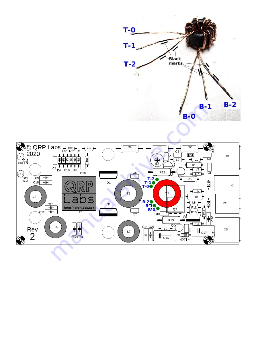
This photograph (right) illustrates the process.
Prefixes T (for Top) and B (for Bottom) are
used to indicate whether the wire comes out
from the top side or the bottom side of the
toroid when it is laying flat on the table.
Wires T-0 and B-0 have continuity.
Wires T-1 and B-1 have continuity and are
labeled with a single black marker stripe.
Wires T-2 and B-2 have continuity and are
labeled with two black marker stripes.
It is utterly critically important to insert these
wires into the correct PCB holes, as labeled in
the diagram below. There are two sets of 3-
holes. The top set of holes is to be connected
to the 3 twisted wires coming over the top of
the toroid. The bottom set of three holes is to be connected to the 3 twisted wires coming from
under the toroid core.
With all this in mind, we can start soldering.
Again, hold the T1 toroid flat against the PCB, orientated as precisely as possible over the white
circle drawn on the PCB silkscreen. Put the correct wires in the correct holes. Pull the wires
through reasonably tightly, still keeping the toroid in position flat on the PCB. Make sure the
labeled wires are in the correct holes, before soldering. It is hard to fix, later!
Now cut wire B-2 on the underside of the PCB, leaving a few mm spare. Scrape the insulation
from the last 5mm or so of the wire. Tin and solder it while it is in place in the hole. You will need
to hold the soldering iron to the joint for more than 10 seconds, firmly, and add more fresh solder
from time to time; the pad is grounded so the ground plane will dissipate heat and make achieving
a good joint more difficult.
Similarly cut wire T-2 with a few mm spare, scrape it, tin and solder it while it is in place in the
hole, holding the iron in position for 10 seconds to ensure all enamel is burned away and there is a
good joint. Now look for resistor R4 at the top of the PCB; hold the DVM probes to the pads of R4
50W QCX PA kit assembly
1.00q
18


