on the PCB. Hold the iron on the joint for at least 10 seconds and then feed in some more fresh
solder. This should ensure a good joint and all the enamel burned away.
Now similarly cut, prepare and solder the other “black marked” wire, which is the one in the hole
nearest to C7. Hold the toroid flat against the PCB in the correct position, while cutting the wire
with a few mm protruding; then scrape the wire and tin it and solder it to the pad, while in place;
hold the iron for 10+ seconds to ensure a good joint with all enamel burned away.
Use a DVM to measure continuity from the middle of the three pins of transistor Q2’s pads, and
the pad at right hand side of capacitor C7. The DVM in resistance mode should measure zero
ohms. If it does not, then you have either mixed up the wires or have a poor joint.
Now cut, prepare, and solder the wire in the bottom left hole, nearest to Q1. Check for continuity
with the DVM, from the middle pin of transistor Q1, to the right hand side of capacitor C7. You
should see continuity here.
Finally, cut, prepare and solder the wire at the top right hole, nearest to C6. Check for good DC
continuity with the DVM, from the middle pin of transistor Q1, to the right hand side of capacitor
C6.
3.7 Wind and install trifilar transformer T1
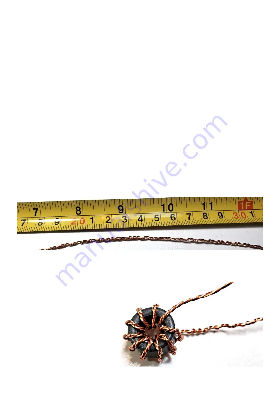
The three remaining wires are to be wound into trifilar transformer T1. They should be twisted
together in much the same way as the bifilar transformer T2 from the previous section. Again, it is
hard to twist three wires neatly and evenly. But again, it is not going to make much difference and
the amplifier will work regardless.
Now wind 10 turns carefully around the remaining ferrite toroid (remember one time through the
center, counts as 1 turn), again try to keep it compact but be careful not to pull hard, scraping the
wires against the toroid which could remove the enamel and cause short circuits later.
In the end you hopefully end up with
something looking like this (see right).
Identification of the wires is similar to the
earlier bifilar transformer T2. First scrape
the last 5mm of the wires, and tin them –
so that you can touch the DVM probes
there to determine continuity.
Find each pair for which continuity exists
and arrange the wires nicely so that the
windings are in order.
Label the wires again by drawing black
felt tip pen marks.
50W QCX PA kit assembly
1.00q
17


