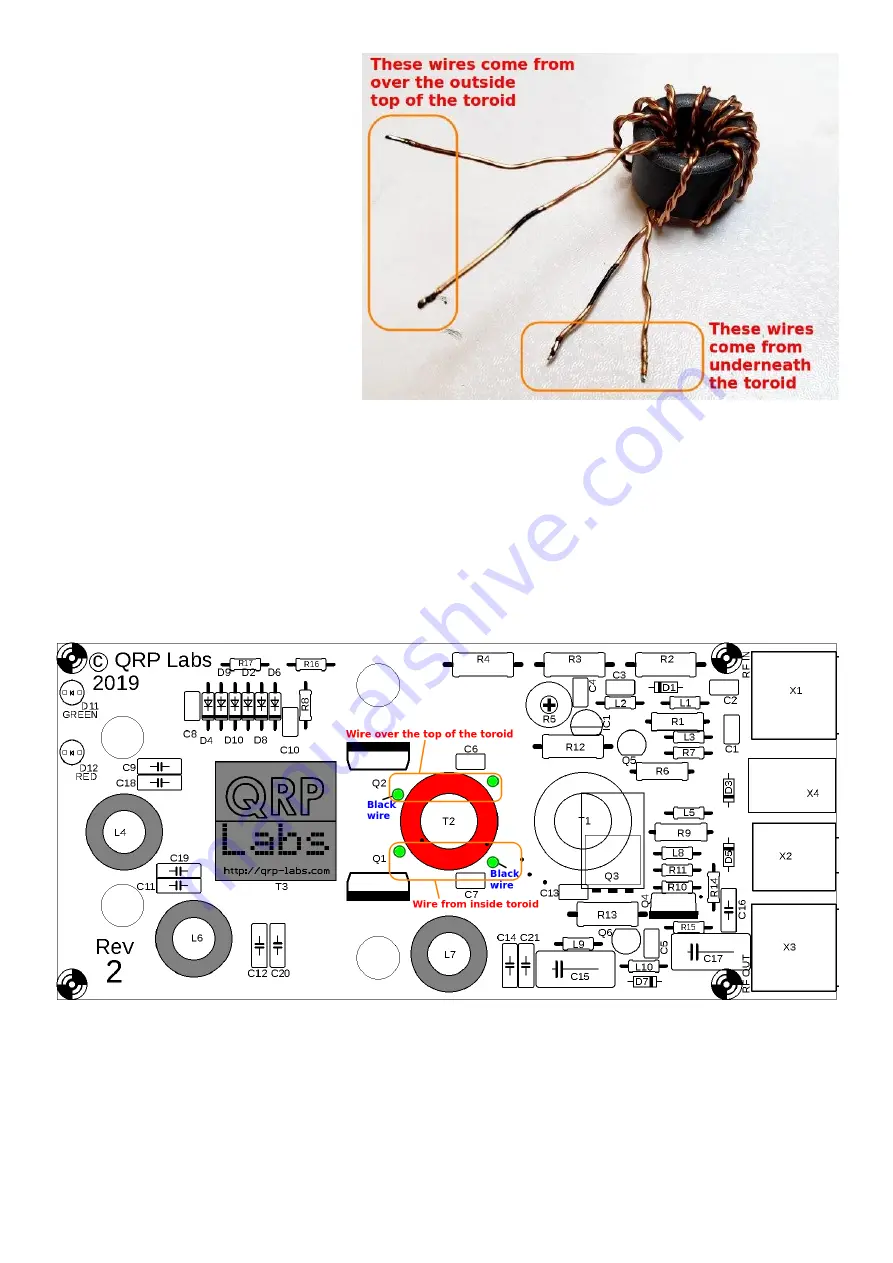
The diagram and explanation below
illustrates the correct wire placement.
It is CRITICALLY IMPORTANT to get
this right!
Now lay the toroid down flat on the
table as shown and identify the wires
which come from the center of the
core, over the top of the outside of the
core; and those which come out from
the underside of the toroid (see right).
All four wires go into holes that are on
the circumference of the outer circle of
the white silk-screen printing on the
PCB.
One black wire, that comes over the
outside of the top of toroid, must be inserted in the hole nearest the “Q2” text on the PCB (the top
left hole). The non-black wire that comes over the top of the outside of the toroid, which is twisted
together with this black wire, must be inserted in the hole nearest C6 (the top right hole).
One non-black wire coming from the underside of the toroid goes in the hole near the “Q1” text.
The corresponding black-marked wire goes in the hole near C7.
In this way, the lower pair of wires (Q1, C7) are from the twisted pair that comes from UNDER the
toroid; the top pair of wires (Q2, C6) are from the twisted pair that comes from the TOP side of the
toroid.
Pull the wires through the holes so that the toroid sits flat on the PCB, and is orientated accurately
with the white ink circle drawn on the PCB silkscreen. The toroid won’t sit perfectly flat of course,
because of the twisted bifilar windings. This is not a problem.
Squeeze the toroid gently to the PCB in the correct position, and cut the black-marked wire
nearest Q2, leaving a few spare mm. Now scrape some enamel from the last 5mm of this wire with
a knife or wire cutter; it does not have to be perfectly scraped but removing some enamel in this
way helps the remaining enamel to burn off easily. Tin it and solder it while it is in place in the hole
50W QCX PA kit assembly
1.00q
16


