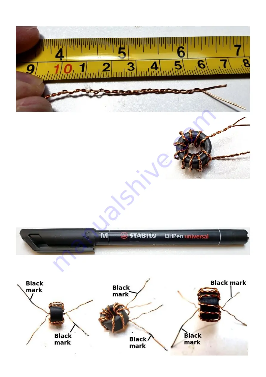
The bifilar wire should end up looking something like this (top scale in inches, bottom scale in cm):
Wind 10 turns around one of the ferrite toroids (remember,
each time the wire passes through the center counts as one
turn). Leave 4-5cm of wire at each end.
Try to wind the wire tightly on the toroid but be careful not to
scratch the enamel which could cause short circuits between
the wires.
In the end it should end up looking something like this (right).
Now comes the tricky business of determining which wire goes
in which hole on the PCB. It has to be done CORRECTLY or
the kit will not work.
Step by step, slowly and carefully, will ensure success.
Scrape and tin the wire ends, just for the purposes of identification of windings using a DVM. Use
the DVM to identify continuity between a pair of wires. This is one of the windings. Use a felt-tip
pen to mark these two wires that have continuity between them. Check again, to make sure you
haven’t mixed up the wires!
Orientate the wires so that the wires with the black mark are at diagonals. These three photos all
show the same thing from different angles and hopefully make it clear.
50W QCX PA kit assembly
1.00q
15


