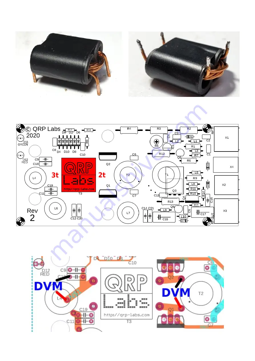
Cut the wires so that the binocular core body stands elevated 5mm from the workbench (below
left). Then scrape the enamel from 5mm of the wire ends, and tin (below right).
Install the transformer in the PCB as shown in red (below). Be VERY sure that the 2-turn primary
winding wire ends are on the right side, nearest to the transistors Q1 and Q2; whereas the 3-turn
secondary winding wire ends must be on the left, near inductor L4.
Now use a DVM, set to resistance mode (or continuity beeper if it has that facility) and hold the
black and red probes on the holes shown in the diagram below labeled “DVM” in blue. You should
measure continuity (zero resistance). If not, check that the wires are properly tinned and soldered.
50W QCX PA kit assembly
1.00q
12


