


Chapter 3 Robot Debugging and Components Maintenance
Document Version V1.1.0 (03-07-2022)
28
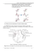
Figure 3-23 Axis J4 module installation diagram
Step 9
Re-thread the signal and power cables at the end pass-through interface to
Axis J3 and connect the interface.
Step 10
Connect the communication and power cables on the Axis J4 module one
after another, fix the cables of Axes J3 ~ J4 with cable ties, and then re-install
the waterproof cover at the rear end.
Step 11
Fill the four countersunk head screws in the inner ring of the module with
Black Power Sealant. Apply a layer of Black Power Sealant on the inner ring of
the flange (the area between screw holes), and then restore the flange end,
and tighten the screws (apply a layer of thread glue when installing the screws)
with a screw torque of 2.4 N·m.
Figure 3-24 Axis J4 flange inner ring
Step 12
Restore the Axis J5/J6 completely, and tighten the fastening screws of the
shell with a screw torque of 2.4 N·m.
3.3.4 Replacement of Axis J3 module
If a problem is detected in the Axis J3 module, remove and replace the Axis J3 module
following the steps below:
Wear ring
Module
rubber plug
Cable holder
Flange inner ring
Countersunk
head screw
Summary of Contents for MS6MT
Page 1: ......


