


Chapter 3 Robot Debugging and Components Maintenance
Document Version V1.1.0 (03-07-2022)
17
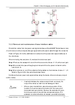
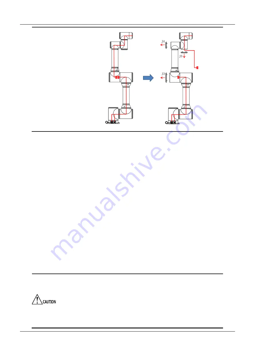
3.2.2 Removal and maintenance of base interface cables
Extend the cables from the power and signal interfaces of the MS6MT Robot base to Axis
J3, and connect to the end pass-through signal cable and power cable through the connector.
Refer to Figure 3-5 for the distribution of cables from the power and signal interfaces of
the robot base.
When removing the axis (Axis J1) modules from the lower part:
Step 1
Remove the waterproof covers from the rear ends of Axes J1~J3 at the lower part.
Step 2
Disconnect the pass-through signal connector from the power connector at the
end of Axis J3.
Step 3
Use scissors to cut off the cable ties fixing cables on the modules of Axes J1 ~ J3.
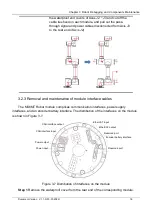
Refer to Figure 3-6 for the cable fixed sheet metal.
Distribute the base power and signal cables along the inside of the robot body, and pull
out the cables.
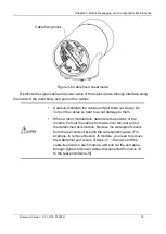
Carefully distribute the cables and pull them out slowly. Do
not pull the cables so hard to avoid damage to them.
When a robot module fails, determine the position of the
module. Pull out the cables from Axis J3 to the rear end of
the determined axis module. Remove the waterproof covers
from the rear ends of axes till the corresponding axis. (For
example, to remove the Axis J2 module, you need to remove
Summary of Contents for MS6MT
Page 1: ......


