background image


July 2018


3-25 


3.5.1


Activating a Marker 


There are two basic marker types, normal markers and delta markers. Normal 
markers are used to measure the frequency/time or amplitude of a point on the 

trace. Delta markers are used to measure the difference between a reference 
point and a selected point on the trace. 


3.5.1.1


Activate a Normal Marker 


  Press 


X


Marker


 and select a marker number. 

Marker

: 1 

5. 

 Press   to turn the selected marker on. 

 Press 

Mode


 and set the marker mode to Normal. 


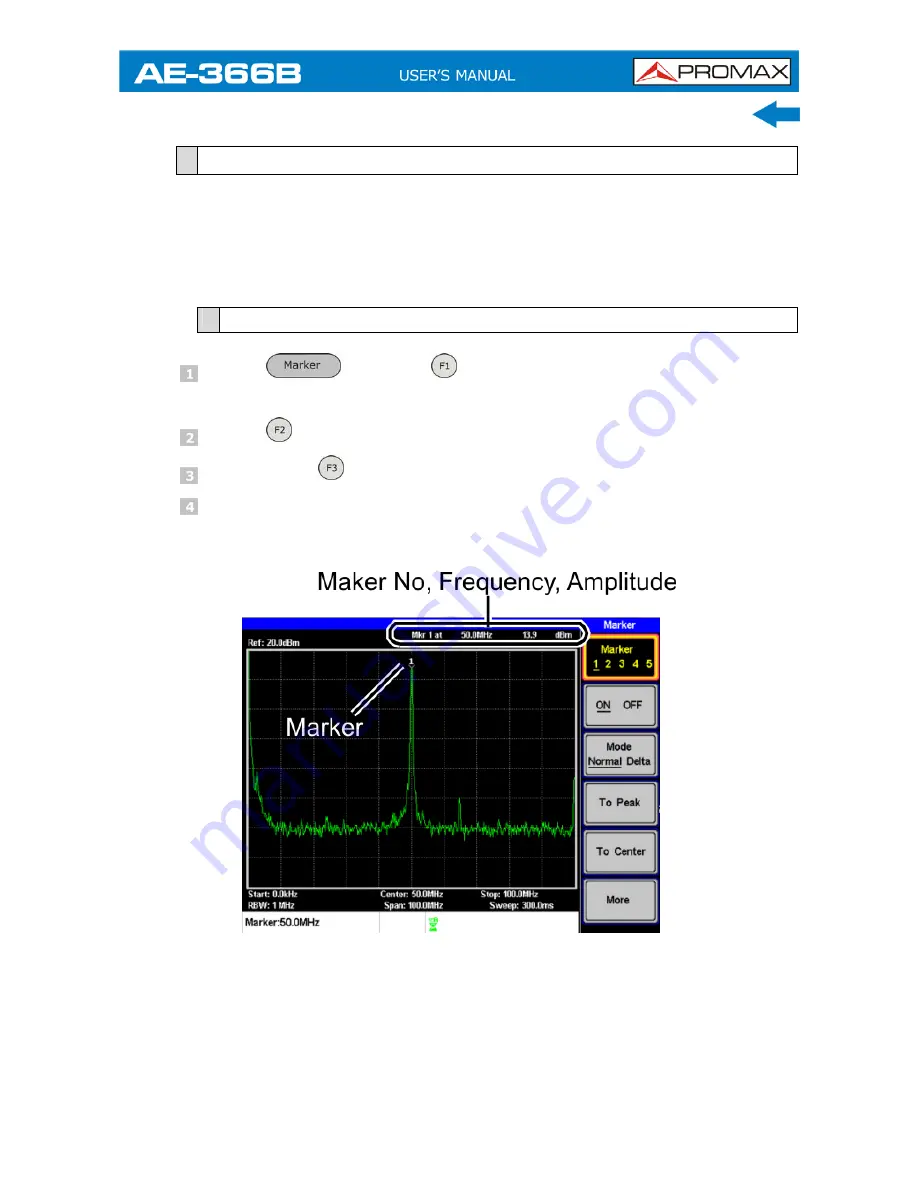
  The display will show the marker on the trace (centered by default) with 

the marker measurement at the top of the display. 


Figure 25. 

Summary of Contents for AE-366B

Page 1: ...AE 366B SPECTRUM ANALYSER 0 MI2007...

Page 2: ...to any chapter by clicking on the title of the chapter in the table of contents Click on the arrow at the top right of the page to return to the table of contents USER S MANUAL VERSION Version Date S...

Page 3: ...Do not block the cooling fan opening Do not disassemble the instrument unless you are qualified Measurement categories EN 61010 1 2010 specifies the measurement categories and their requirements as f...

Page 4: ...t as unsorted municipal waste Please use a separate collection facility or contact the supplier from which this instrument was purchased Please make sure discarded electrical waste is properly recycle...

Page 5: ...2 3 Zero Span 3 19 3 2 4 Last Span 3 19 3 3 Amplitude Settings 3 20 3 3 1 Reference Level 3 20 3 3 2 Amplitude Units 3 21 3 3 3 Scale Div 3 21 3 4 Autoset 3 22 3 4 1 Using Autoset 3 22 3 4 2 Limiting...

Page 6: ...iew 3 51 3 11 Save Recall Files 3 53 3 11 1 Save Recall Setup 3 53 3 11 2 Save Recall Trace Data 3 54 3 11 3 Save Recall Limit Lines 3 55 3 11 4 Saving an Image File Hardcopy 3 55 3 11 5 Hardcopy Setu...

Page 7: ...2018 4 3 10 BW Commands 4 71 4 3 11 Display Commands 4 72 4 3 12 Preset Commands 4 73 4 3 13 System Commands 4 73 5 FAQ 5 74 6 SPECIFICATIONS 6 75 6 1 Specifications AE 366B 6 75 6 2 Default Settings...

Page 8: ......

Page 9: ...zer The AE 366B has all the basic features of our more advanced models but in a smaller package designed especially for education Figure 1 1 2 Main Features Performance 150 kHz 3 GHz 100 kHz resolutio...

Page 10: ...menu icons VGA video output RS 232C USB 2 0 Host port for data storage USB 2 0 Device port for the virtual com port communication 1 3 Package Content Opening the box Figure 2 Check that your package...

Page 11: ...for the current function frequency amplitude and marker information Function keys The to function keys directly correspond to the soft keys on the right hand side of display Menu keys Frequency Sets t...

Page 12: ...s and tests Pass Fail limit lines BW Sets the resolution bandwidth Trace Sets traces and trace related functions Display The Display key configures the split screen windowing mode and the basic displa...

Page 13: ...nt values in steps select listed items RF input terminal RF input port Accepts RF inputs Maximum input 30 dBm 20 dBm measurable Input impedance 50 Maximum DC voltage 25 V N type female Numeric keypad...

Page 14: ...RS 232 RS232 9 pin DSUB port USB B USB B Device port USB 1 1 2 0 VGA VGA video out port Supports SVGA 480X640 Power Socket Power Socket 100 240V 50 60Hz 15W Max Security Slot Kensington type security...

Page 15: ...The Soft menu keys are associated with the F1 to F6 function keys to the right of the display Trace Icons Displays the color of each active trace and the trace mode of each active trace Entry Message...

Page 16: ...e default settings Lastly the Conventions sections will introduce you to the basic operating conventions used throughout the user manual 2 2 1 Tilting the Stand The AE 366B has two adjustable tabs at...

Page 17: ...r local PROMAX distributor Power Down Press the power button to power down Figure 10 2 2 3 Software Update The AE 366B allows the software to be updated by end users Before using the AE 366B please ch...

Page 18: ...ssful is displayed the software has successfully completed the update procedure Reboot the system when the update procedure has finished by cycling the power button Check the software version again to...

Page 19: ...er the Ports COM LPT node Figure 12 NOTE If the USB driver installation fails you can try to manually install the driver You can tell that the driver hasn t been installed if you see the USBSerial ico...

Page 20: ...input description below for more details Toggle State Pressing this menu key will toggle the state Notice that any soft menu key that can be toggled will have the active parameter underlined Toggle S...

Page 21: ...menu Active Function Pressing this type of menu key will activate that function The menu key will be highlighted to show it is the active function Parameter input Figure 14 Parameter values can be ent...

Page 22: ...anti clockwise decreases the value The scroll wheel is usually used for values that highly variable such as the center frequency settings Directional arrows Use the directional arrows to select discr...

Page 23: ...cy and centers the display to the center frequency Press X Center and enter the frequency and unit Range 0 kHz 3 GHz Default 1 5 GHz Figure 16 3 1 2 Start and Stop Frequency The start stop frequency f...

Page 24: ...n change when the span settings are used The stop frequency must be set higher than the start frequency for spans 0 3 1 3 Center Frequency Step The Step function sets the step size of the center frequ...

Page 25: ...July 2018 3 17 By default the center frequency step size is equal to 10 of the span Press X Step and set the center frequency step size Range 1 kHz 3 GHz Figure 18...

Page 26: ...span will alter the start and stop frequencies Press X Span and enter the span frequency range and unit Range 0 kHz 3 GHz Default Span 3 GHz Figure 19 3 2 2 Full Span The Full Span function will set...

Page 27: ...omain characteristics of the input signal at the center frequency The horizontal axis is displayed in the time domain Press X Zero Span The span changes accordingly Figure 20 Amplitude modulation NOTE...

Page 28: ...ude attenuation scale and external gain loss 3 3 1 Reference Level The reference level defines the absolute level of the amplitude on the top graticule in voltage or power Press X Ref Level and enter...

Page 29: ...n be set from dBm dBmV or dBuV Press X Units to change the amplitude units Units dBm dBmV dBuV 3 3 3 Scale Div Sets the logarithmic units for the vertical divisions Press X Scale repeatedly to select...

Page 30: ...mum amplitude and then shows it in the display 3 4 1 Using Autoset Press X Autoset Amplitude Over the full amplitude range Span Over the full span range Figure 23 Before Autoset default state Figure 2...

Page 31: ...o Man Enter the amplitude limit with the number pad and Enter key Range 50 to 20 dBm 3 4 3 Limiting the Autoset Horizontal Search Range You can change the frequency span limit in the display to get a...

Page 32: ...rences between reference markers The AE 366B can automatically move a marker to various locations including the peak signal center frequency and start stop frequency Other marker operations regarding...

Page 33: ...a markers are used to measure the difference between a reference point and a selected point on the trace 3 5 1 1 Activate a Normal Marker Press X Marker and select a marker number Marker 1 5 Press to...

Page 34: ...osition of the selected marker or in the center of the display if the selected marker has not yet be activated The marker measurement is located at the top of the display under the normal marker measu...

Page 35: ...o directly enter the frequency of the marker position Figure 28 3 5 1 4 Move Marker to Preset Locations The currently selected marker normal marker or delta marker can be moved to a number of preset p...

Page 36: ...rker to Stop Marker to Step Marker to Ref Level 3 5 2 Move marker to Trace The Marker Trace function moves the selected marker to the currently active trace Press X Marker and select a marker number P...

Page 37: ...ivated both normal and delta markers can be turned off at the same time with the All Mrk Off function Press X More X All Mrk Off and turn all the markers off 3 5 3 Show Markers in Table The AE 366B ha...

Page 38: ...uency and the amplitude of the marker Figure 30 3 5 3 1 Edit Markers in Marker Table While the Marker Table function is the active function the position of each marker and delta marker can be edited w...

Page 39: ...Marker to Peak Move the active marker to the highest peak The highest peak can be either found once or continuously Press X Marker and select a marker number Press X Peak Search To continually search...

Page 40: ...visible on the display Next Peak Right Searches for the next peak to the right of the marker Next Peak Left Searches for the next peak to the left of the marker Min Search Searches for the lowest peak...

Page 41: ...e The Peak Table function will display up to 5 peaks The amplitude and frequency for each peak is listed Press X More X Peak Table and turn the peak table on Press Peak Sort and set the sorting type F...

Page 42: ...The bottom half of the screen shows the peak table with the peak marker no frequency and amplitude Figure 35 3 34 July 2018...

Page 43: ...uency bandwidth the target channel occupies Range Between 0 Hz 3 GHz 0 Hz excepted Channel Space The frequency distance between each main channel Range Between 0 Hz 3 GHz Adjacent channel bandwidth 1...

Page 44: ...ain channel power to power in the adjacent channel Figure 36 Operation Setting up the main channel Press ACPR and turn ACPR on Any other measurement mode will automatically be disabled The display spl...

Page 45: ...ress Channel Setup and set the following Main CH BW Set the bandwidth of the main channel Main CH Space Specify the channel spacing NOTE The main channel bandwidth and space settings are shown in the...

Page 46: ...annel offset of the 2nd adjacent channel NOTE The adjacent channel bandwidth and space settings are shown in the setup area at the bottom of the screen not on the soft key icons Figure 39 Move Channel...

Page 47: ...the channel Figure 40 Operation Setting up the main channel Press X OCBW and turn OCBW on Any other measurement mode will automatically be disabled The display splits into two screens The top shows t...

Page 48: ...n the setup area at the bottom of the screen not on the soft key icon Figure 42 Move Channels Up Down Press the again or press Return repeatedly to return to the start of the Measure menu tree Press C...

Page 49: ...e input signal is above below or within the limit lines The limit lines can be manually edited using 10 frequency points from the start to the stop frequencies 3 7 1 Activate a Limit Line Press to ent...

Page 50: ...ct the limit line you wish to edit Limit High Low Press Edit Table and turn the edit table on The AE 366B is split into two screens The top screen shows the trace and the selected limit line high or l...

Page 51: ...rt to their default frequency and amplitude values To delete a point from the editing table press Delete The whole points including the frequency value and the amplitude are removed This command reduc...

Page 52: ...he display Pass Fail NOTE At least one limit line high or low must be turned on to enable testing If only high limit line is on each trace point has to be lower than the high limit line to get a PASS...

Page 53: ...that is used to separate signal peaks from one another The narrower the RBW the greater the capability to separate signals at close frequencies But it also makes the sweep time longer under specific f...

Page 54: ...e Trace menu Figure 47 Trace Type Icon The type of trace used determines how the trace data is stored or manipulated before being displayed The analyzer updates each trace according to the type of tra...

Page 55: ...he display and stores trace data The trace data can be restored by pressing View Operation Press X Trace and choose a trace Trace A B C Select the trace type Clear Write Peak Hold View Blank More Min...

Page 56: ...ce A A const A Subtracts an offset from trace A Press Trace Math and select a trace math function A B A B A A B A A const A A const A If A const A or A const A was selected set the constant offset val...

Page 57: ...July 2018 3 49 Figure 48 Average Off Figure 49 Average On 8x...

Page 58: ...t levels Press X LCD Dimmer and use either the number pad the scroll wheel or arrow keys to set the brightness 3 10 2 Setting a Display Line Reference Level Line The Display Line function is used to s...

Page 59: ...able to view two different sweep ranges on the display at the same time using a split screen view The top and bottom view can have independent sweep ranges amplitudes spans and other settings However...

Page 60: ...able the split spectrum view Turning Half Upper on will automatically turn Half Lower off Turning Half Lower on will automatically turn Half Upper off If Alternate Sweep is turned on each sweep will a...

Page 61: ...p Setup data contains all the data necessary to recall the state of the AE 366B to known state Setup data contains the following data Center frequency Start frequency Stop frequency Step frequency Ref...

Page 62: ...led Save To save the current trace data press X Save Trace Data Press Source Trace and select the source Source A B C Press Destination and select the memory location to save to Destination 1 5 Press...

Page 63: ...recall pre saved upper and lower limit lines press X Limitln from and choose a memory location to recall from with the arrow keys Limit line 1 5 Press to execute the recall 3 11 4 Saving an Image Fil...

Page 64: ...copy key is pressed Ink Normal This is the normal default image setting Ink Saving This will invert all the colors on the display so that the file will conserve ink when printed Press and choose the i...

Page 65: ...Number XX digit serial number HW Version Hardware version FW Version Firmware version SW Version Software version Language Shows the language number as seen in the System Language menu Operation Press...

Page 66: ...The language option sets the icon display language Press X Language to bring up the Language menu Choose a system language The language number is the number that will be displayed in the system infor...

Page 67: ...ctor RS232 male port Equipment side connector RS232 female port Baud Rate 9600 19200 38400 57600 115200 Parity None Even Odd Space Mark Multidrop Stop bit 1 1 5 2 Data bit 5 6 7 8 The AE 366B can use...

Page 68: ...rk Multidrop Stop Bit 1 1 5 2 Data 5 6 7 8 4 1 2 Remote Control Function Check Invoke a terminal application such as MTTTY Multi Threaded TTY To check the COM port No see the Device Manager in the PC...

Page 69: ...tree Each keyword node of a SCPI command is separated by a colon For example the diagram below shows an SCPI sub structure and a command example Figure 53 Command types There are a number of different...

Page 70: ...1 5 freq NRf unit Unit kHz MHz GHz Note The unit can be omitted defaults to currently set unit 2 5 mhz refl NRf unit Unit dBm dBmV dBuVNote The unit can be omitted defaults to currently set unit 30 d...

Page 71: ...ops the sweep Example si Name sn Description Continues a stopped sweep Example sn Name ts Description Resets the sweep and starts it once i e sweeps one time Example ts 4 3 3 Frequency Commands Name m...

Page 72: ...Syntax meas freq stp Parameter freq Stop frequency Return parameter freq Returns the stop frequency and unit Example meas freq stp 100 mhz Sets the stop frequency to 100MHz Query example meas freq stp...

Page 73: ...rence level in the currently selected unit from the meas refl unit command Return parameter refl Returns reference level and unit Example Meas refl 10 Sets the reference level to 10 dBm for unit dBm Q...

Page 74: ...freq Returns the frequency and unit of the selected marker Example meas mark norm freq1 1 5GHz Name meas mark norm level Description Queries the amplitude of the selected normal marker Query syntax me...

Page 75: ...r amp Returns the amplitude and unit of the selected delta marker Example meas mark delta level1 10 0dBm Name meas mark tomin Description Sets the selected marker to the minimum peak Syntax meas mark...

Page 76: ...k Mode Parameter mode 5 Minimum hold mode Example meas tra 1 1 Sets trace A to clear and write mode Name meas tra avg on Description Turns the average function on and sets the number of averages for t...

Page 77: ...s returned in three lots TraceA TraceB TraceC The units are in decibels If the selected trace is not active os will be returned for each trace point 4 3 8 Power Measurement Commands Name meas acpr Des...

Page 78: ...on or off or queries its status Syntax meas ocbw on off Query syntax meas ocbw On OCBW mode on Parameter Return parameter Off OCBW mode off Example meas ocbw on Turns the OCBW function on Name meas oc...

Page 79: ...test off 0 Fail Return parameter 1 Pass Query Example meas Imtline passfail 0 Name meas Imtline on Description Turns the limit lines on Syntax meas Imtline on Name meas Imtline off Description Turns...

Page 80: ...eter NRf Example con swt 1500 4 3 11 Display Commands Name con disp split upper Description Turns on the split window function and sweeps the top window Syntax Con disp split upper Name con disp split...

Page 81: ...settings This is the equivalent to pressing the Preset key Syntax con preset 4 3 13 System Commands Name con sys ser Description Returns the serial number Query syntax con sys ser Return parameter str...

Page 82: ...ften the trace is updated on the screen To increase the sweep time try reducing the span or using a wider RBW setting I cannot see the trace on the screen If you cannot see the trace on the screen the...

Page 83: ...e 85 dBc Hz typical 500 kHz offset RBW 30 kHz Sweep time 1 5s Span 1MHz 1GHz Inherent Spurious Response less than 45dBc 40 dBm Ref Level typical less than 50 dBc AMPLITUDE Reference Level Input Range...

Page 84: ...z OPERATING ENVIRONMENTAL CONDITIONS Operating Temperature From 5 to 45 C Guaranteed at 25 5 C without soft carrying case Operating Humidity Less than 45 C 90 RH Storage Temperature 20 to 60 C less th...

Page 85: ...rt Frequency 0Hz Stop Frequency 3GHz CF Step Auto Span Span 3GHz Amplitude Reference level 30 0dBm Scale Div 10 Units dBm Autoset Amp Floor Auto Span Auto Marker Marker Off Peak Search N A Meas ACPR O...

Page 86: ...6 78 July 2018 Trace Trace A Clear Write Average Off Display Full Display Active Display line off Memory N A Preset N A Hardcopy N A Hardcopy Setup Ink Normal System N A...

Reviews: