background image

3350F Series Operation Manual 61 


3. Press  ENTER  to  set  the  next  setting  step.  Repeat  the  same  Process  for  each   

Setting steps. Up to 16 steps can be entered.   

Once the T1 and T2 settings have been entered for the final   


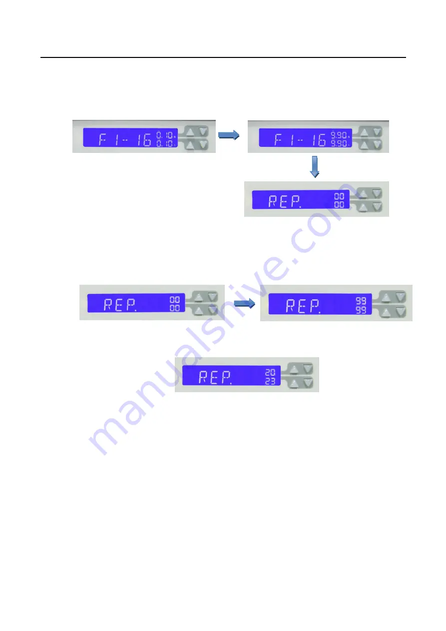
Step press the STORE button. The LCD will now show REP. 


4. The REP function allows the auto-sequence to be repeated a number of times.   

Both  sets  of  arrow  keys  are  used  to  set  the  number  of  repeats  between  0  and   

9999 times. Once the Number of repeats has been set press the STORE button to   


Save the auto-sequence. 


Example: The following screen shot shows the   

 Number of repetitions has been set to 2023   


Summary of Contents for 3350F Series

Page 1: ...3350F Series High power Electronic Load Operation manual S N 9003350F04 REV I...

Page 2: ...re using the meter Caution risk of electric shock CAT IV Is for measurements performed at the source of the low voltage installation CAT III Is for measurements performed in the building installation...

Page 3: ...s that the concentration of the hazardous substance in all homogeneous materials in the parts is below the relevant threshold of the SJ T 113632006 standard SJ T 11363 2006 Indicates that the concentr...

Page 4: ...ck hazard that could result in personal injury FUSES Only fuses with the required rated current voltage and specified type normal blow time delay etc should be used Do not use repaired Fuses or short...

Page 5: ...Safety standards following IEC 61010 1 2010 EN 61010 1 2010 EMC standard EN 61326 1 2006 EN 61326 2 1 2006 EN 55011 2009 A1 2010 EN 61000 3 2 2006 A1 2009 A2 2009 EN 61000 3 3 2008 EN 61000 4 2 2009 E...

Page 6: ...STOP AND ALARM 20 2 21 LOAD WIRE INDUCTANCE 21 CHAPTER 3 OPERATION 24 3 1 FRONT PANEL DESCRIPTION 1 24 3 2 OPERATING INSTRUCTIONS 25 3 3 FRONT PANEL DESCRIPTION 2 54 3 4 FRONT PANEL DESCRIPTION 3 56 3...

Page 7: ...109 5 11 POWER SUPPLY OPP TESTING 111 5 12 POWER SUPPLY SHORT TESTING 113 APPENDIX A GPIB PROGRAMMING EXAMPLE 115 APPENDIX B 3350F USB INSTRUCTION 118 APPENDIX C 3350F LAN INSTRUCTION 120 APPENDIX D...

Page 8: ...on 20 Fig 2 11 3350F series Rear panel 20 Fig 2 12 Waveform example Generate unstable oscillation 22 Fig 2 13 Length of wiring 23 Fig 3 1 3350F Series High Power Front Panel 24 Fig 3 2 3350F Series Hi...

Page 9: ...5 Table 4 3 REMOTE CONTROL LIMIT COMMAND SUMMARY 75 Table 4 4 STAGE COMMAND SUMMARY 76 Table 4 5 SYSTEM COMMAND SUMMARY 77 Table 4 6 MEASURE COMMAND SUMMARY 77 Table 4 7 Auto sequence command list 78...

Page 10: ...t has an input from 0 120A and 0 60V current and voltage operating range respectively The power contour of 3350F series The prodigit 3350F Series high power electronic Load can be controlled locally a...

Page 11: ...g 1 1 3350F Power Contour Fig 1 2 3351F Power Contour 1800W CONTOUR 120 A 30 40 60 90 60 30 20 0 4 Current Voltage 0 1 15 0 0 15 0 225 1200W CONTOUR 120 A 20 30 60 80 60 20 15 0 6 Current 0 1 10 0 3 0...

Page 12: ...ur Fig 1 5 3354F Power Contour 1800W CONTOUR 360 A 30 60 90 180 60 20 10 0 7 Current 0 1 5 0 0 3 Voltage 0 15 1800W CONTOUR 240 A 30 34 38 60 120 60 30 15 0 7 Current 0 1 7 5 0 0 35 0 175 Voltage 1200...

Page 13: ...e of constant current the 3350F Series Electronic load will sink a current in accordance with the programmed value regardless of the input voltage see Fig 1 7 Fig 1 7 Constant Current mode 600W CONTOU...

Page 14: ...h the programmed resistance setting see Fig 1 8 I V LOAD CURRENT INPUT VOLTAGE RESISTANCE SETTING Fig 1 8 Constant Resistance mode CV Mode At constant voltage mode the 3350F Series Electronic Load wil...

Page 15: ...re six parameters to generate dynamic wave form or pulse wave form the 3350F Series Electronic Load will sink current from power source proportional to the dynamic wave form the dynamic wave form defi...

Page 16: ...e the transition from one setting to another is small the small Signal bandwidth of the load limits the minimum transition time for all programmable slew rates Because Of this limitation the actual tr...

Page 17: ...8 PRODIGIT Fig 1 12 Rise Time Transition Limitation...

Page 18: ...matic voltage sense capability 1 2 8 Full protection from over power over temperature over voltage and reverse polarity 1 2 9 Analog programming input capability at rear panel 1 3 Accessories 1 3 1 33...

Page 19: ...Slew rate 8mA 500mA uS 80mA 5000mA uS 8mA 500mA uS 80mA 5000mA uS 0 016A 1A uS 0 16A 10A uS 0 016A 1A uS 0 16A 10A uS 0 024A 1 5A uS 0 24A 15A uS 8mA 500mA uS 80mA 5000mA uS Resolution 2 20mA uS 2 20m...

Page 20: ...tage Meter General Short Circuit Current 120A 120A 240A 240A 360A 120A Temperature Coefficient 100ppm typical Power 100Wmax 100Wmax 100Wmax 100Wmax 100Wmax 100Wmax Operating Temperature 2 0 40 Dimensi...

Page 21: ...the correct cord Refer to check line voltage to check the line voltage selection and fuse type 2 2 Check line voltage The 3350F Series high power load can operation with 115 230Vac input as indicated...

Page 22: ...priate Specifications fuse which indicated in Table 1 1A 2 3 3 Reinstall fuse holder and connect the power cord Fig 2 2 FUSE RECEPTACLE Never fail to turn off the power of this product and disconnect...

Page 23: ...Series high power load is equipped with feet and tilt stands installed and is ready for used as a bench instrument The feet provide a good viewing angle for bench top use 2 6 Rack mount The 3350F Seri...

Page 24: ...arity of the connection and connect the load wire to the output Terminal of the equipment under test 2 12 Repair If the instrument is damaged please attach a tag to the instrument to identify the owne...

Page 25: ...ter in one by one configuration The RS 232C BAUD RATE can be set in the front panel it will be lit the GPIB address when press the SYSTEM button Press it again it will be lit the BAUD RATE Fig 2 4 335...

Page 26: ...umber of devices including the controller is no More than 15 2 17 3 2 The maximum length of all cable is no more than 2 meters times The Number of devices connected together up to 20 meters Maximum 2...

Page 27: ...current slew rate can be set independently from front panel operation or remote programming The slew rate determines a rate at which the current changes to a new programmed value The slew rate can be...

Page 28: ...nge II the slew rate of range I range II RISE FALL slew rate are listed in chapter 1 5 specifications 5 HIGH LOW HIGH IH IL ON OFF ON T T ON LOAD V A TYPICAL POWER SUPPLY OUTPUT VOLTAGE B LOAD ON OFF...

Page 29: ...t Emergency stop signal and Alarm signal are isolated The emergency stop signal is active low when emergency stop signal goes to low the 3350F Series Load will go to load off immediately The Alarm sig...

Page 30: ...th the current Variation of 2 A s the voltage generated by the wire inductance Will be 20 V The negative polarity of the load input terminal is the reference potential of the external Control signal T...

Page 31: ...ly output Voltage x10 CH3 LOAD Input Voltage x10 Fig 2 12 Waveform example Generate unstable oscillation You must be careful especially when the slew rate setting is high or switching is performed Usi...

Page 32: ...ased accordingly the generated voltage Will be Reduced even the inductance of load wiring can not be reduced In the case of DC operation also the phase delay of the current may cause instability in Th...

Page 33: ...Series load the memory Store Recall GPIB RS 232 LAN USB remote programming are described in the mainframe operation manual Please refer to the mainframe s operation manual for mainframe store recall a...

Page 34: ...ce is Constant Current CC Constant Resistance CR Constant Voltage CV and Constant Power CP Each time the MODE key is pressed the Operating mode is changed The actual operating mode selected is indicat...

Page 35: ...lected test function SHORT test selected left display will show Short OPP test selected left display will show OPP OCP test selected left display will show OCP During the test the left display will sh...

Page 36: ...volts V If CP mode is selected the right display provides setting in watts W 3 2 7 2 LIMIT Each press of the LIMIT button changes the middle LCD text The Sequence and the corresponding setting value s...

Page 37: ...test along with the setting value is as follows OPP Press Start pressing the red START STOP button starts the test PSTAR power start point right display provides setting in watts W PSTEP power steps r...

Page 38: ...OAD button lit LOAD ON load sinks according to the preset values LOAD button unlit LOAD OFF the load does not sink current Turning the LOAD OFF does not affect the preset values When the LOAD ON state...

Page 39: ...arrow keys In STATIC mode the user can switch between High and low load levels during Operation In DYNAMIC operation CC CP modes only the preset high and low levels are Used to define the dynamic wav...

Page 40: ...13 2 Constant Resistance CR mode The High and Low levels of load resistance can be preset on the right 5 Digit LCD The LED will be lit indicating the setting value is ohms 3 2 13 3 Constant Voltage CV...

Page 41: ...alue to be entered On first press Of the LIMIT key the button will illuminate and V Hi will be displayed on the middle LCD The setting is made with the rotary knob and can be read from the lower LCD D...

Page 42: ...5 digit LCD Display the unit is V The V Lo set range from 0 000 V to 60 000V step 0 001V by Rotating the Setting knob Setting Upper limit current IH Middle 5 digit LCD display I Hi right 5 digit LCD D...

Page 43: ...lower limit power WL Middle 5 digit LCD display W Lo lower 5 digit LCD Display the unit is W The W Lo set range from 0 0 W to 1800 0W step 0 1W by Rotating the Setting knob Setting NG ON OFF When exce...

Page 44: ...ss limits key to set the V Hi and V Lo voltage upper and lower limits of the GO NG CV mode press limits key to set the I Hi and I Lo Current upper and lower limits of the GO NG Go NG NG Current Voltag...

Page 45: ...he DYNAMIC waveform to be set On first press of the DYN key the button will illuminate and T Hi will be displayed On the middle LCD The value is adjusted with the rotary knob and can be read From the...

Page 46: ...display will show setting value the unit Is ms The T Hi Set range from 0 050 ms to 9999 ms step 0 001ms by rotating the Setting Knob Setting level Low period Middle 5 digit LCD display will show T Lo...

Page 47: ...The CONFIG key allows the sense function to engage automatically or switched ON The CONFIG key also enables the LOAD to automatically turn ON OFF When A voltage level is reached The polarity symbol c...

Page 48: ...oltage is valid for CC CR CP operating Modes The adjusted LDon voltage will not operate in CV mode Note 2 The LDon LOAD ON voltage setting cannot be lower than the LDoff LOAD OFF voltage If 0V is requ...

Page 49: ...greater Than the input voltage Load ON voltage setting the Electronic load current begin to Load on Setting Load OFF voltage the middle of the 5 digit LCD display will show LDoFF Right the 5 digit LCD...

Page 50: ...uminate The message SHORT PRESS START will be shown across the 3 displays Each press of the SHORT key moves the menu on one step The left and Middle LCDs show the currently selected test parameter as...

Page 51: ...CONTI on right 5 digits LCD display the Setting range is CONTI means continue 100mS to 10000mS step 100ms by Clockwise rotate the Setting knob The short test will be no time limitation when setting to...

Page 52: ...key allows the parameters of an Over Current Protection test to be entered The OCP test will ramp up the load current in steps to validate the Device Under test s DUT protection and behavior A voltage...

Page 53: ...e is 0 00A to the full scale of the CC mode specification The setting Is by rotating the setting knob ISTEP setting the increment step current point The LCD display shows OCP on left 5 digit LCD displ...

Page 54: ...TART STOP button while the OCP PRESS START text is displayed During the Test The middle LCD will show run and the actual current being Taken will be displayed On the lower LCD Note 1 The message OCP E...

Page 55: ...tinued and the OPP ERROR message will be Displayed Pressing the OPP key once will cause the button to illuminate The message OPP PRESS START will be shown across the 3 displays Each press of the OPP b...

Page 56: ...etting range is 0 0W to the full scale of the CP mode Specification The setting is by rotating the setting knob PSTEP setting the increment step power The LCD display shows OPP on left 5 digit LCD dis...

Page 57: ...ton while the OPP PRESS START text is displayed During the test The middle LCD will show run and the actual power being taken will be displayed on The lower LCD Note 1 The message OPP ERROR will be di...

Page 58: ...e refer to the preceding sections for more information on the SHORT OCP OPP tests 3 2 21 Knob and Knob key Right Knob Setting digit can flash clockwise add setting value Left Knob Setting digit can fl...

Page 59: ...ity of the DUT prior to connection and testing The negative load terminal should be connected to ground if testing a positive Output power supply This is normally achieved when the negative output of...

Page 60: ...r The I monitor is provided as a terminal It is designed to enable the user to Monitor the Electronic Load s input current or short current The I monitor s signal Is 0V to 10V This signal is proportio...

Page 61: ...ad Drain source Gate Fig 3 4 an equivalent circuit in terms of the current monitor Connecting the I monitor to an oscilloscope When you connect this product to an oscilloscope please ensure the correc...

Page 62: ...nual 53 Fig 3 6 Wrong Connections to an oscilloscope If the probes connection is reversed as shown in Fig 3 6 a large current would flow through the Probe and the internal circuitry of the oscilloscop...

Page 63: ...rface To bring back the unit to front panel control the local button on the Right hand side of the mainframe can be pressed 3 3 2 GPIB Card The LCD will permanently show GPIB if this computer interfac...

Page 64: ...ing the NG function according to the voltage Current or power limits set via the LIMIT menu 3 3 8 STATE T2 Display The lower digits relate to the memory STATE location in normal mode There are 10 memo...

Page 65: ...ng the system button once allows the GPIB address to be changed by using The arrow keys Pressing the system button again allows the RS232 baud rate to Be adjusted With the third press of the system bu...

Page 66: ...keys are used to change the address Once the required address is reached press enter or store button to save the New address The exit key can be pressed to return to the normal screen 3 5 1 2 To set...

Page 67: ...in which you will store the set up 3 Press the store key on the mainframe The store key starts flashing If you no longer wish to store a setting you can press the exit button or Wait about 20 seconds...

Page 68: ...ocation has been selected press the STORE key This example below Shows bank 01 state 01 After pressing store key the LCD will revert to the Normal message Step 3 Use the mains switch on the front pane...

Page 69: ...e auto sequence numberThe XX Part is the test step 1 to 16 is possible 2 Once the auto sequence number has been selected the Memory location of the First test step can be selected The Arrow keys next...

Page 70: ...the final Step press the STORE button The LCD will now show REP 4 The REP function allows the auto sequence to be repeated a number of times Both sets of arrow keys are used to set the number of repea...

Page 71: ...y tested If during a given test step the values measured are Outside the preset limits and the NG Function has been enabled then The LCD will flash NG And the test is suspended The user can press the...

Page 72: ...S16 in order If all tests Steps have been completed then the LCD will show PASS Example 2 Once the edit mode has been used to set the 16 step auto sequence the user can Press the TEST key If the test...

Page 73: ...ued 3 2 Press EXIT to end the test and back to normal mode Enter Exit Stop NG Yes Normal Mode End No Step Step 1 No PASS FAIL Show PASS Show FAIL PASS FAIL 2 3 Exit Yes 4 4 If test is GO than step is...

Page 74: ...IT W_Lo 0 0 W CP L Preset 0 00W SENSE Auto CP H Preset 0 00W LD ON 1 0 V T HI 0 050 mS LD OFF 0 500 V T L0 0 050 mS CONFIG POLAR LOAD RISE 8 0mA uS SHORT Disable DYN FALL 8 0mA uS OPP Disable OCP Disa...

Page 75: ...R LOAD RISE 0 016A uS SHORT Disable DYN FALL 0 016A uS OPP Disable OCP Disable Table 3 3 3352F initialize Item Initial value Item Initial value CC L Preset 0 000 A V_Hi 60 000 V CC H Preset 0 000 A V_...

Page 76: ...ONFIG POLAR LOAD RISE 0 024A uS SHORT Disable DYN FALL 0 024A uS OPP Disable OCP Disable Table 3 5 3354F initialize Item Initial value Item Initial value CC L Preset 0 000 A V_Hi 60 000 V CC H Preset...

Page 77: ...he maximum wire gage 10 can be used in this application 3 7 3 Insert the wire into the input terminal This is the most convenient way to Connect the load input and D U T The maximum wire gage AWG14 ca...

Page 78: ...b no longer continues rotating in the way 3350F RANGE I RANGE II FULL SCALE LOAD CURRENT 12A 120 A CURRENT RANGE 0 12A 120A METER RESOLUTION 0 2mA 2mA COURSE FINE LOAD CURRENT ADJUSTMENT knob CC Mode...

Page 79: ...m 0 041m 0 0041m CV Mode 0 01V 0 001V 0 0001V 0 1V 0 01V 0 001V CP Mode 1W 0 1W 0 01W 10W 1W 0 1W 3353F RANGE I RANGE II FULL SCALE LOAD CURRENT 24A 240 A CURRENT RANGE 0 24A 240A METER RESOLUTION 0 4...

Page 80: ...01V 0 001V 0 0001V 0 1V 0 01V 0 001V CP Mode 1 002W 0 102W 0 009W 10 02W 1 002W 0 102W 3356F RANGE I RANGE II FULL SCALE LOAD CURRENT 12A 120 A CURRENT RANGE 0 12A 120A METER RESOLUTION 0 2mA 2mA COU...

Page 81: ...oon as the temperature of 3350F Series heat sink greater than 85 degree the Over temperature protection is occurred the Digital Current Meter s LCD display will indicate OTP at same time the 3350F Ser...

Page 82: ...pply or an rechargeable battery charge discharge characteristic testing The function capability of rear panel remote control interface not only can set the load level and load status but also can read...

Page 83: ...NL LDONV SP NR2 NL LDOFFV SP NR2 NL CC CURR HIGH LOW SP NR2 NL CP HIGH LOW SP NR2 NL CR RES HIGH LOW SP NR2 NL CV VOLT HIGH LOW SP NR2 NL TCONFIG SP NORMAL OCP OPP SHORT NL OCP START SP NR2 NL OCP ST...

Page 84: ...V VOLT HIGH LOW NL TCONFIG NL 1 NORMAL 3 OPP 2 OCP 4 SHORT OCP START NL OCP STEP NL OCP STOP NL VTH NL OPP START NL OPP STEP NL OPP STOP NL STIME NL OCP OPP Table 4 2 REMOTE CONTROL QUERY COMMAND SUMM...

Page 85: ...F 1 ON PRES SP ON OFF 1 0 NL PRES NL 0 OFF 1 ON SENS SP ON OFF AUTO 1 0 NL SENS NL 0 OFF AUTO 1 ON LEV SP LOW HIGH 0 1 NL LEV NL 0 LOW 1 HIGH DYN SP ON OFF 1 0 NL DYN NL 0 OFF 1 ON CLR NL ERR NL NG NL...

Page 86: ...1 15 m STATE n BANK REMOTE NL RS232 USB LAN command LOCAL NL RS232 USB LAN command NAME NL XXXXX Table 4 5 SYSTEM COMMAND SUMMARY Measure command COMMAND RETURN MEAS CURR NL MEAS VOLT NL MEAS POW NL...

Page 87: ...n NL n 1 16 1 16 TOTSTEP SP n NL Total step n 1 16 1 16 SB SP m n NL m 1 10 n 1 15 m STATE n BANK T1 SP NR2 NL 0 1 9 9 s 0 1 9 9 sec T2 SP NR2 NL 0 0 9 9 s 0 0 9 9 sec SAVE NL Save File n data REPEAT...

Page 88: ...DOFfv SP NR2 NL PRESet CC CURR HIGH LOW SP NR2 NL PRESet CP HIGH LOW SP NR2 NL PRESet CR RES HIGH LOW SP NR2 NL PRESet CV VOLT HIGH LOW SP NR2 NL PRESet TCONFIG SP NORMAL OCP OPP SHORT NL PRESet OCP S...

Page 89: ...t OCP STEP NL PRESet OCP STOP NL PRESet VTH NL PRESet OPP START NL PRESet OPP STEP NL PRESet OPP STOP NL PRESet STIME NL Table 4 2B REMOTE CONTROL QUERY COMMAND SUMMARY LIMIT RETURN LIMit CURRent HIGH...

Page 90: ...NL 0 LOW 1 HIGH STATe DYNamic SP ON OFF NL STATe DYNamic NL 0 OFF 1 ON STATe CLR NL STATe ERRor NL STATe NO SP GOOD NL 0 GO 1 NG STATe NG NL 0 GO 1 NG STATe PROTect NL STATe CCR SP AUTO R2 NL Note1 S...

Page 91: ...eering unit m A uS 5 Power engineering unit W Auto sequence avilable for all module AUTO SEQUENCE COMMAND NOTE RETURN FILE SP n NL n 1 9 1 9 STEP SP n NL n 1 16 1 16 TOTSTEP SP n NL Total step n 1 16...

Page 92: ...data of the GPIB command it can not be omitted The contents of the symbol indicts the command can be used or not It depends on the testing application This symbol means option For example LOW HIGH mea...

Page 93: ...load level change or dynamic load can be programmed of RISE and FALL are completely independent 2 3350F will set to the maximum value of the model automatically when the FALL which has been set is ov...

Page 94: ...att Description This command is for setting the required value of Watt and the unit is W CR RES HIGH LOW Syntax PRESet CR RES HIGH LOW SP NR2 NL PRESet CR RES HIGH LOW NL Purpose Set and read the valu...

Page 95: ...sing value I STEP of OCP test OCP STOP Syntax PRESet OCP STOP SP NR2 NL PRESet OCP STOP NL Purpose Set and read the maximum value of OCP test Description This command is used for setting the maximum v...

Page 96: ...ime set to 0 it means that have no the time limit and continue to be short circuited The unit is milli second ms OCP Syntax OCP Purpose Set read OCP testing current Description This command is used fo...

Page 97: ...L LIMit VOLtage HIGH LOW NL VH VL SP NR2 NL VH VL NL Purpose To set the upper lower limit value of threshold voltage Description This command is to set the upper lower limit value of threshold voltage...

Page 98: ...ng the Loading Operation mode the return value 0 1 2 3 are meant to be CC CR CV CP CC 0 CR 1 CV 2 CP 3 3350F V V V V Table 4 9 module for each series STATe SHORt SP ON OFF Syntax STATe SHORt SP ON OFF...

Page 99: ...L Purpose Set and read the LOW and HIGH of Load Description LEV LOW is a low level value of current on CC mode It is a low level value of resistance on CR mode It is a low level value of voltage on CV...

Page 100: ...NG check function enable or disable Description To set the function of NG judgment opens when POWER ON When setting for POWER OFF the function of NG judgment will not be implemented STATe POLAR POS NE...

Page 101: ...Recall the status of Loading which had been saved in the 3rd of Memory If 3350F is operated it will be operated in the BANK which has been shown on the display SYStem STORe SP m n Syntax SYStem STORe...

Page 102: ...l number as table 4 11 MODEL 3350F 3351F 3352F 3353F 3354F 3356F Table 4 11 MODEL NUMBER SYStem REMOTE Syntax SYStem REMOTE NL Purpose Command to enter the REMOTE status only for RS232 Description Thi...

Page 103: ...the five numbers of current meter and the unit is Ampere A MEASure VOLTage Syntax MEASure VOLTage NL Purpose Read the voltage which is loading of Load Description Read the five numbers of current met...

Page 104: ...the electronic load connected to the DC power supply Local sensing is used in application where lead lengths are relatively short or where load regulation is not critical The 5 digit voltage Meter of...

Page 105: ...ng compensates for the voltage drop in applications that require long lead lengths The 5 digit voltage Meter of 3350F electronic load measures the voltage of Vsense input Terminal automatically so the...

Page 106: ...eration the 3350F can operate as a static load with switchable high and low current Levels It is also possible to operate the load dynamically enabling the user to adjust sink Current with time 5 3 1...

Page 107: ...Fall time Tb Ihigh Ilow Fall slew rate Please see Fig 1 12 for more information on slew rates The time the waveform is high Thigh and the time the waveform is low Tlow can Also be adjusted The diagra...

Page 108: ...is selected CC 5 3 4 2 Pressing the Preset Key 13 once will cause the Button to illuminate 5 3 4 2 1 Pressing the LEVEL key 12 LED once will illuminate Select LEVEL Hi Adjusted by the rotary knob and...

Page 109: ...urrent according to The battery voltage In CV mode the electronic load will sink the current that is Needed to reach the desired voltage The CV mode is therefore ideal for checking The charge current...

Page 110: ...Manual 101 DC CURRENT SOURCE ELECTRONIC LOAD CV MODE INPUT V I Lo INPUT VOLTAGE CONSTANT VOLTAGE SETTING A B C A B C V I CV SETTING LOAD CURRENT POWER SUPPLY CURRENT LIMIT TESTING Fig 5 5 Constant Vo...

Page 111: ...t LEVEL Lo Adjusted by the rotary knob and arrow key 21 can be read from the right Display during Setting 3 000V 5 4 3 2 2 Pressing the LEVEL key 12 LED once will illuminate Select LEVEL Hi Adjusted b...

Page 112: ...uit cause the power supply to shut down This is because the power supply is trying to deliver the 50A at a voltage level that is too low The answer to this problem is not to use CC mode but to use CR...

Page 113: ...ill cause the button to illuminate 5 5 2 2 1 Pressing the LEVEL key 12 LED once will illuminate Select LEVEL Hi Adjusted by the rotary knob and arrow key 21 can be read from the right Display during S...

Page 114: ...tain a constant power the output current will need to increase over time to compensate for the reducing voltage Fig 4 7b Operating the 3350F series electronic load in CP mode is ideal for testing the...

Page 115: ...Operating Instructions Example PSU 5 V 3 A CC mode Level HI 10 00W Level 5 00W 5 6 2 1 These can be selected in turn by pressing the MODE key 8 LCD will illuminate According to the operating mode is...

Page 116: ...OAD button lit Load on Pressing the LEVEL Key 12 LED Once will illuminate Select is LEVEL Hi 5 6 2 5 Pressing the LEVEL key 12 LED Once will off Select is LEVEL Lo 5 7 Constant current source operatio...

Page 117: ...scharge current testing Fig 5 9 Zero Volt loading connection 5 9 Parallel operation The following is a rule for a multiple output power supply connects to the 3350F series Electronic Loads Rule The po...

Page 118: ...Limit Key function to setting I_Lo 0A 5 10 1 3 Setting OCP test press OCP key to the next step 5 10 1 4 Setting start load current 0A press OCP key to the next step 5 10 1 5 Setting step load current...

Page 119: ...shows FAIL 5 10 2 Remote control OCP EX REMOTE Set Remote TCONFIG OCP Set OCP test OCP START 3 Set start load current 3A OCP STEP 1 Set step load current 1A OCP STOP 5 Set stop load current 5A VTH 0 6...

Page 120: ...to setting W_Lo 0W 5 11 1 3 Setting OPP test press OPP key to the next step 5 11 1 4 Setting start load watt 0W press OPP key to the next step 5 11 1 5 Press up key set step load watt 0 1W press OPP k...

Page 121: ...L 5 11 2 Remote control OPP EX REMOTE Set Remote TCONFIG OPP Set OCP test OPP START 3 Set start load watt 3W OPP STEP 1 Set step load watt 1W OPP STOP 5 Set stop load watt 5W VTH 0 6 Set OPP VTH 0 6V...

Page 122: ...ep 5 12 1 3 Press down key setting V Hi voltage to 1 000V press Short key to the next Step 5 12 1 4 Press down key setting V Lo voltage to 0V press Short key to the next Step 5 12 1 5 Press START STOP...

Page 123: ...ODIGIT 5 12 2 Remote control SHORT EX REMOTE Set Remote TCONFIG SHORT Set SHORT test STIME 1 Set short time 1ms START Start SHORT testing TESTING Ask Testing 1 Testing 0 Testing End STOP Stop SHORT te...

Page 124: ...clude the decl h HEADER FILE to C LANGUAGE include stdio h include dos h include math h include decl h NI GPIB CARD HEADER FILE main char ouster 20 rdbuf 15 spec 10 int i ch load Assign unique identif...

Page 125: ...buffer ibrd load spec 20 if spec 3 9 printf n 3350F specification error Set the channel 1 preset off current sink 1 0 amps and load on commands to the load ibwrt load chan 1 pres off curr low 0 0 cur...

Page 126: ...190 REM Get the 3350F series module load specification 195 REM 200 wrt NAME CALL ibwrt load wrt 210 rd space 20 CALL ibrd load rd 215 REM 220 REM Set the channel 1 preset off current sink 1 0 amps an...

Page 127: ...118 PRODIGIT Appendix B 3350F USB Instruction 1 Install the USB DRIVER select USB SETUP PL 2303 Driver Installer exe...

Page 128: ...Operation Manual 119 2 After the installation connect the 3350F and PC with USB Then select the item USB to Serial Port COM3 set the BAUD RATE and Flow control to 115200bps and Hardware to control 335...

Page 129: ...HUB 2 Run the ETM EXE which bellows the path of the LAN on the CDROM drive it will show as fig D2 1 if not please press F5 to search again or check the first step was succeed or not FIG D2 1 3 It will...

Page 130: ...ient Enable 6 6 Socket port of HTTP setup 80 6 7 Socket port of serial I O 4001 TCP Server 6 8 Socket port of digital I O 5001 TCP Server 6 9 Destination IP address socket port TCP client and UDP Conn...

Page 131: ...ber key program number 6 Press BANK up down key to select memory bank 7 Press STATE up down key to select memory state 8 Press ENTER to next step 9 Repeat 6 8 to edit Step of sequence 10 Press STORE t...

Page 132: ...ion mode Press the mode key to CC mode 3 Set the range Press RANGE key to force range 2 4 Press Load ON 5 Set the current value as step 1 8 and store to memory bank 3 state 1 8 6 Press EDIT key of 335...

Page 133: ...124 PRODIGIT Testing Waveform...

Reviews: