16
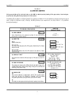
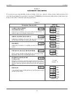
USER LINEARISATION PARAMETERS
The parameters listed on this page are used to implement the linearisation curve on the process value represented by the DC
linear output of a transmitter. The parameters affect the measured PV only if the ‘User Linearisation’ feature is ‘Enabled’ and if
the input type is DC Linear. That is, the PV measured using Thermocouple or RTD is not affected by the linearisation
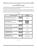
parameters. The Table 8.1 below lists the user linearisation parameters.
Visit www.ppiindia.net for technical notes on USER LINEARISATION for detailed understanding of the parameters /
terminologies used for describing the parameters in this section.
Table 8.1
Settings
(Default Value)
Parameter Description
Enable / Disable user linearisation feature.
USER LINEARIZATION
Select number of segments for the purpose of input
PV
curve
linearisation by setting the number of total break points.
TOTAL BREAK POINTS
Protection password for access to the linearisation related
parameters. Set to
333
as valid password.
USER LINEARIZATION SETTING CODE
1 to 32
(Default : 2)
0 to 9999
(Default : 0)
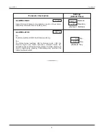
BREAK POINT NUMBER
Select the break point for which the X, Y co-ordinates are to be set.
1 to 32
(Default : 1)
-19999 to 30000
(Default : Undefined)
ACTUAL VALUE FOR
BREAK POINT (X CO-ORD)
Set the actual measured (X co-ordinate) value.
Set the computed or derived (Y co-ordinate) value.
DERIVED VALUE FOR
BREAK POINT (Y CO-ORD)
-19999 to 30000
(Default : Undefined)
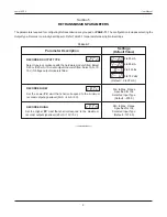
Yes
No
(Default : No)
User Manual
neuro 100EX
Section 8

