1
FRONT PANEL LAYOUT
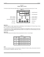
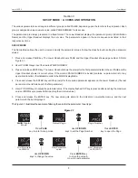
The indicator front panel comprises of digital readouts, LED indicators and tactile keys as shown in Figure 1.1 below.
Figure 1.1
Upper Readout
Lower Readout
Enter Key
Up Key
Down Key
Page Key
Alarm-3 Status
Alarm-1 Status
PPI
neuro 100 EX
ACK
OPR
AL3
AL4
AL1
AL2
Alarm-2 Status
Alarm-4 Status
Alarm Acknowledge Key
Operator Key
READOUTS
The Upper Readout is a 5 digit, 7-segment bright red LED display and usually displays the PV (Process Value). In Set-up
Mode, the Upper Readout displays parameter values/options.
The Lower Readout is a 5 digit, 7-segment bright green LED display and usually displays Process Value Units. In case of any
active Alarm(s), the Lower Readout flashes Alarm Status information. In Set-up Mode, the Lower Readout displays the names
(identifier tags) for the parameters.
INDICATORS
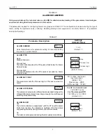
The front panel comprises 4 LED indicators that show Alarm status. Refer Table 1.1 below for details.
KEYS
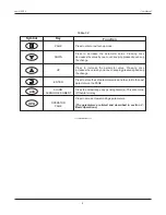
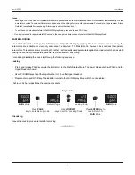
There are six tactile keys provided on the front panel for configuring the indicator, setting-up the parameter values and
selecting Operation / Display Modes. Refer Table 1.2 below.
Table 1.1
Flashes while Alarm-1 is active.
AL1
AL2
Flashes while Alarm-2 is active.
LED
Status
AL3
Flashes while Alarm-3 is active.
AL4
Flashes while Alarm-4 is active.
User Manual
neuro 100EX
Section 1


