


Operating manual liquid ring vacuum pumps and compressors series TRH - TRS - TRM - TRV - SA & Systems type HYDROSYS - OILSYS
9
6 - STORAGE INSTRUCTIONS
After receipt and inspection, if not immediately installed, the unit must be repackaged and stored.
For a proper storage proceed as follows:
- store the pump in a location that is closed, clean, dry and free of vibrations
- do not store in areas with less than 5°C temperature (for lower temperature it is necessary to completely drain the
pump of any liquids that are subject to freezing).
POSSIBILITY OF FREEZING!
Where the ambient temperature is less than 5°C it is recommended to drain the pump, piping, separator, heat
exchanger, etc. or add an anti-freeze solution to prevent damage to the equipment.
It is possible to use as antifreeze a mixture of surface-active glycol or other suitable products making sure
they are compatible with both pump gaskets and elastomers.
- fill the pump with a rust-preventative liquid that is compatible with the pump gaskets and elastomers. Rotate the
shaft by hand to impregnate all internal surfaces. Drain the excessive liquid from the pump and associated piping
(see chapter 11).
Please note that the pumps with cast iron internal parts have been treated at the factory, prior to shipment, with a
rust-preventative liquid: this liquid is capable of protecting the pump against rust for a period of 3 to 6 months.
A further solution, for long term storage, is to fill the pump with the rust inhibitor, rotate the pump shaft by hand to
eliminate any air pockets (the liquid must be suitable with gasket, elastomers and pump materials).
- plug all openings that connect the pump internals to the atmosphere
- protect all machined surfaces with an anti-rust material (grease, oils, etc.)
- cover the unit with plastic sheet or similar protective material
- rotate pump shaft at least every three months to avoid possible rust build-up or seizing
- keep the pump in a dry and clean place not subjected to vibrations caused by other sources
- pump accessories should be subjected to similar procedure.
7 - INSTALLATION INSTRUCTIONS
CAUTION!
Avoid installing the unit in narrow areas and lacking of ventilation where unfavourable conditions for the
personnel may take place. Allow the personnel a good visibility of the pump assembly by providing a proper
lighting.
CAUTION!
A proper pump installation must not transmit vibrations to ambient in the permanent presence of personnel.
Information to determine the piping sizes and floor space requirements can be obtained from dimension drawings and
other engineering data. The information required is:
- size and location of suction and discharge flanges
- size and location of service liquid connection and connections for cooling, heating, flushing, draining, etc.
- location and size for mounting bolts for monoblock pump and/or baseplate and/or frame.
In the event additional accessories are required to complete the installation such as separators, piping, valves, etc. refer
to chapters 7.2 to 7.8.
Proper lifting devices should be available for installation and repair operations.
Pump assembly should be installed in an accessible location with adequate clear and clean space all around for
maintenance, so that an efficient and proper installation can be made.
It is important to have proper room around the unit for ventilation of motor and air cooled radiator, if applicable. Avoid
installing the unit in hidden locations, dusty and lacking of ventilation (minimum 0,6 metres of empty room around).
Select a mounting pad that will minimise vibrations or torsion of the pump baseplate or frame. It is generally preferred to
have a concrete base or sturdy steel beams. The installation must not transmit vibrations to the pump.
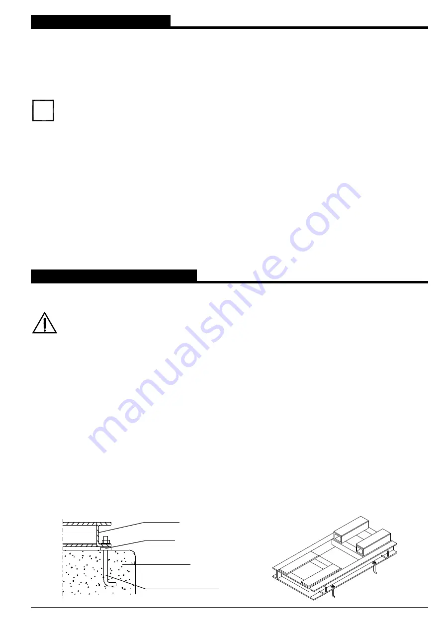
It is important to provide adequate anchor bolting for the pump frame or baseplate to be firmly attached to the
foundations (see fig. 5).
ANCHOR BOLT
CONCRETE
SPACER
BASEPLATE
Fig. 5
i