


Operating manual liquid ring vacuum pumps and compressors series TRH - TRS - TRM - TRV - SA & Systems type HYDROSYS - OILSYS
36
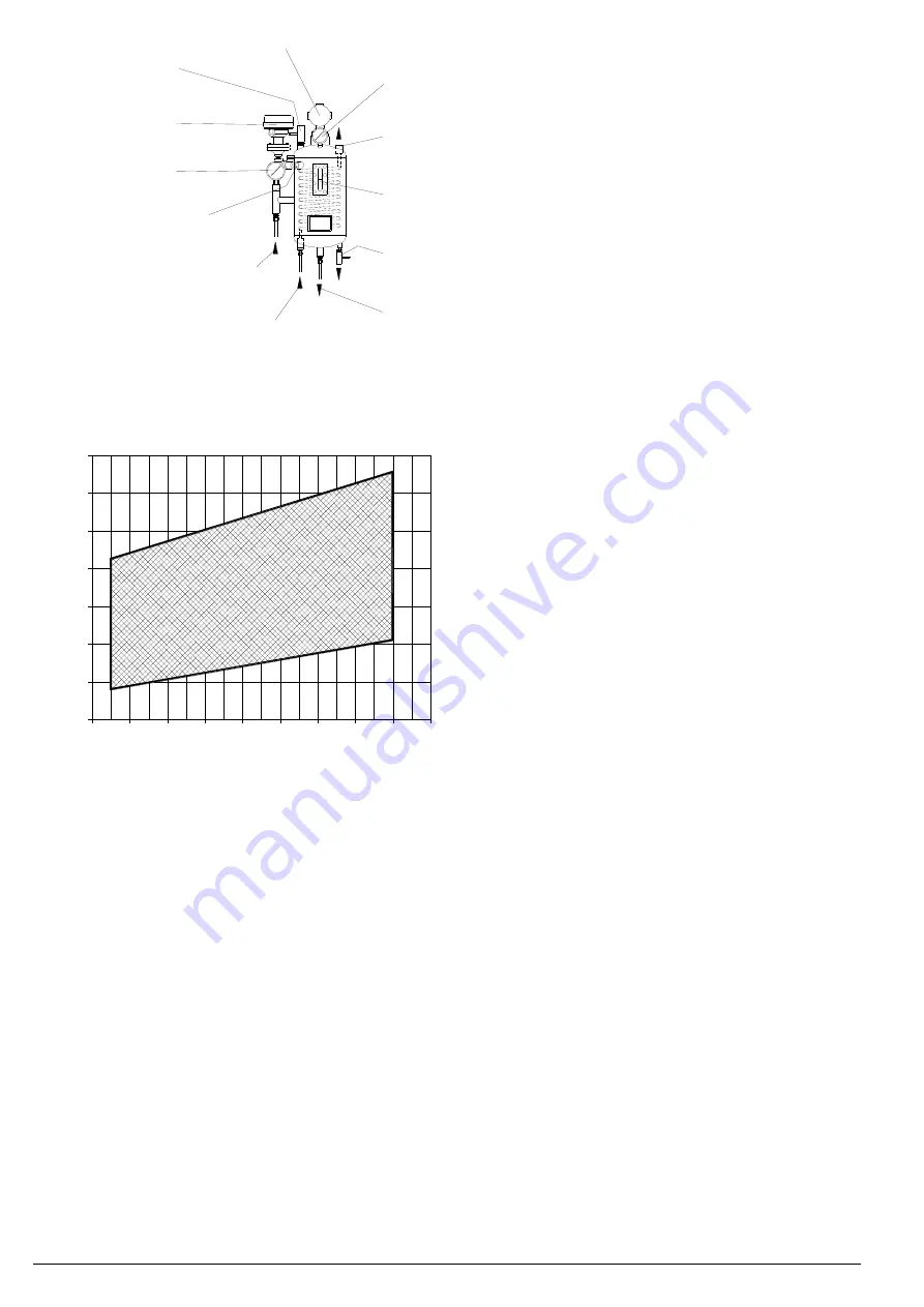
Fig. 37
Typical example of seal tank,
pressurised, cooling liquid and
instrumentation. (Instrument
location can vary)
NOTE:
Tank installation
must be at least 1 m
above the rotating
pump shaft
Tab. 7 - REQUIRED LIQUID FLOW TO FLUSH
MECHANICAL SEALS FROM OUTSIDE
SOURCE
mm = installed shaft seal diameter
bar = maximum pump working pressure (total of inlet
pressure and pump generated pressure as
measured at pump discharge flange)
l/1’ = required liquid flow (lit/min) for single seals or
double in series type seals (tol/-25%
depending upon temperatures)
NOTE: DOUBLE quantity of liquid flow for
double mechanical seals back-to-
back type.
CAUTION: Flushing liquid PRESSURE for back-to-back
double seals must be min 0.5 bar over the
max pump working pressure, while NOT more
than 0.3 bar over the atmospheric pressure in
case of double seals in series (TANDEM).
100
mm
16 mm
bar
l/1'
4
2
0
2
6
8
4
3
6
5
14
12
10
16
18
8
7
9
Minimum level sensor
Pressure switch
Tank fill plug
Temperature gauge
Liquid level (must be higher than
return liquid level from pump)
Inlet liquid (coming back from
mechanical seals)
Inlet cooling liquid
Outlet cooling liquid
Drain
Outlet liquid going to
mechanical seals
Gauge
Tank pressure plug