


Operating manual liquid ring vacuum pumps and compressors series TRH - TRS - TRM - TRV - SA & Systems type HYDROSYS - OILSYS
33
paramount importance for a successful pump installation, it must be installed by qualified personnel familiar with every
details of the application and with system set-up.
All flushing systems MUST use tubing with diameters equal or larger than the connections provided on the pump, buffer
liquid must be compatible with the pumped product. Pressure on the buffer liquid should always be constant and/or high
enough to cover the entire pump performance.
In
the case of ‘once through’ seal flushing (buffer liquid not recycled), it is very important the regulation and control of
pressure in the seal housing. In the double seal case it is recommended to adjust the buffer liquid pressure with a flow
regulating valve installed after the seal housing while reading pressure on a gauge installed between the seal housing
and the valve. Avoid controlling buffer liquid pressure before the seal housing, reading the pressure before the seal
housing is NOT recommended as it could lead to wrong conclusions which could be cause for serious damages.
With an adequate seal tank in the system (see fig. 37) a closed loop seal flushing, containing possible leakages is
provided. Adequate controls and/or instrumentation will provide pressure and liquid level controls in the tank to indicate
the conditions of the sealing system. Increase of liquid level (or pressure) is indication of product leaking through the
pump seal. Decrease of liquid level (or pressure) is indication of buffer liquid leaking inside the pump or to the
atmosphere through the outside seal, in which case the leakage is also visible.
The liquid to be used in the seal tank must offer full compatibility with the pumped liquid in the event the seal at pump
side will leak, (for example when the two liquids will mix there must not be any dangerous chemical reactions) as well
the liquid must offer good lubricating characteristics and good heat dissipation. Some good examples of suitable buffer
liquids are water, vaseline oils or vegetable oils.
Pressure in the seal tank is often kept with pressurised Ozone or Nitrogen bottle. Cooling of the buffer liquid in the loop
(picks up friction heat from the seal faces) is achieved with fresh liquid through the cooling coil fitted inside the seal
tank. Seal tank is provided with Inlet & Outlet connections for sealing liquid. DO NOT reverse these two connections;
the liquid circulates by natural heat convection (warm liquid moves upward and cold liquid downward), reversing the
connections would prevent the start of such natural phenomenon. The buffer liquid outlet connection going to pump seal
housing is at bottom of tank while the return connection is approximately at the middle of the tank.
Checking of proper liquid circulation is done while pump is in service; the piping at seal housing connection should be
colder by 3 to 5°C than the outlet tubing exiting the seal housing going to the tank. If this is not the case simply change
the tubing on the seal housing (connect tubing from inlet to the outlet and vice versa) do not change the connections on
the tank. Sometimes this adjustment is required because the rotation of the mechanical seal (and at times peculiar seal
design) generates an hydraulic pressure that could be opposite and higher than the natural. O
nly in ‘field’ check one
can be assured of the correct liquid circulation. Monitoring the pressure in the seal tank with pressure switches or
pressure gauges and/or controlling the liquid level in the tank allow the verification of possible seal leakages and prompt
corrective actions can be taken when required.
Use good quality gauges to monitor the pressure, with good dial and scale graduation adequate for good reading in the
anticipated pressure range. As a minimum use liquid filled gauges with dial size of minimum 60 mm and 2.5 accuracy.
Additional data and information may be requested from Pompetravaini or its local representative if required.
Incorrect pressure of seal housing could cause severe damage to the rotating parts. To minimise seal system
malfunctions avoid pressure fluctuations in the seal loop as well as in the pump operating pressure.
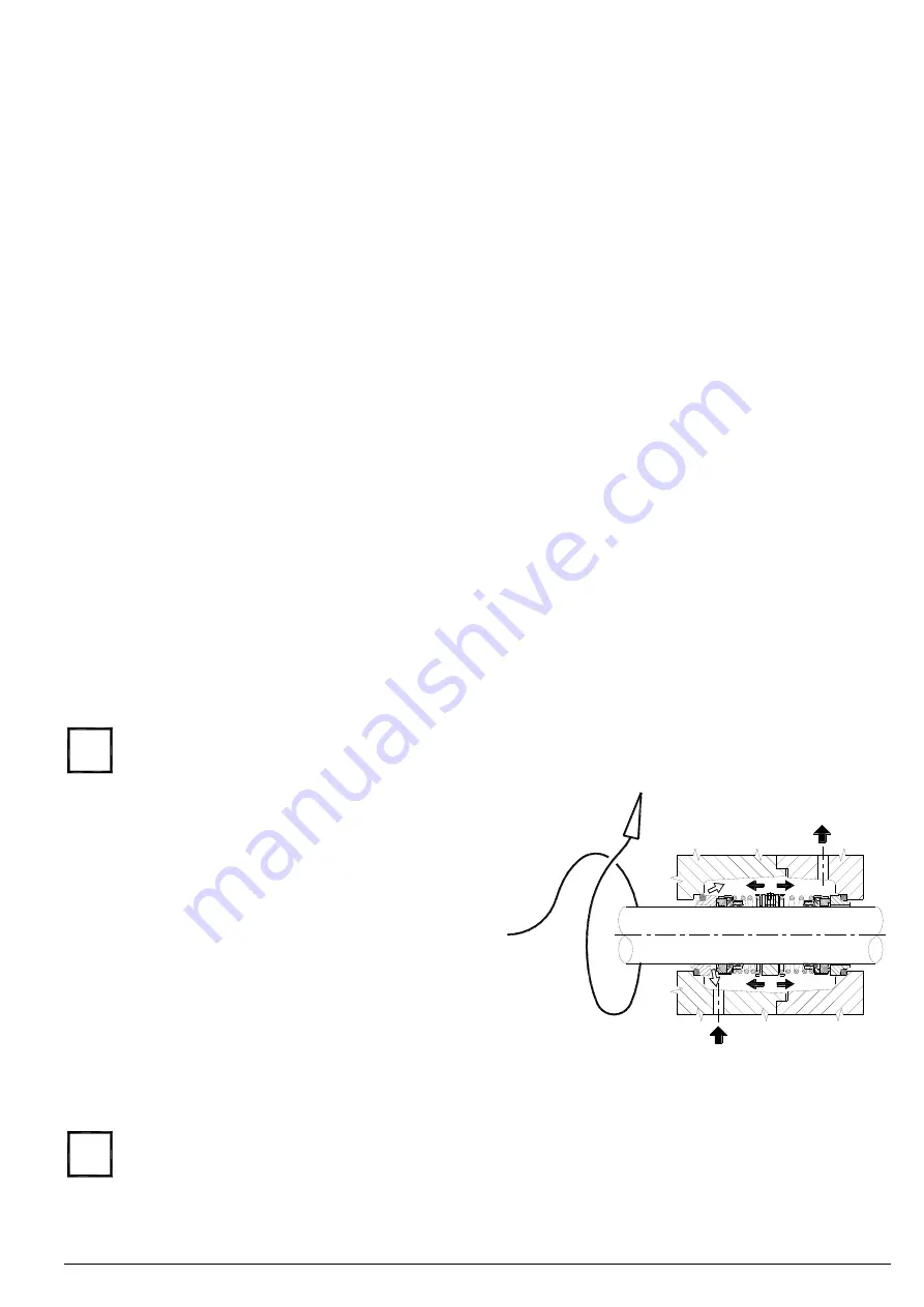
Seal housing with double mechanical seals back-to-back
type, must always have a pressure such that the inside seal
(closer to pump impeller) will not be pushed out of its seat by
the total pump pressure (suction plus pump operating
pressures) even when pump is in stand-by mode. Flushing
liquid therefore must be at least 0.5 bar over the maximum
pump discharge pressure throughout its performance.
A lower pressure, even if for a moment, will cause the
stationary part of internal seal to come out of its seat and the
pumped liquid will mix with the flushing liquid due to the
higher pressure inside the pump, see fig. 31.
In the case of double seals in series (Tandem) the pressure
of the flushing liquid should be as low as possible but high
enough to provide good flow in the circuit. High pressures
(over 0.3 bar over the atmospheric pressure) may push the
stationary seat of mechanical seal at product side (closer to pump impeller), out of its seat (especially when pump is at
rest without pressure), therefore flushing liquid would mix with the product inside the pump following seal system
damage.
Incorrect pressure in sealing system is the most common cause for seal system failure, therefore a continued
monitoring with prompt corrective actions are necessary.
Required flow and pressure for buffer liquid are listed in tab. 7 and/or contact Pompetravaini and/or seal supplier.
Standar
d mechanical seals supplied with our pumps meet ISO 3069/UNI EN 12756 standards, see pump “Disassembly
and Assembly Instructions” for overall dimensions. Special or non-standard seals can be installed after proper
i
i
Fig. 31