PCL
Pleiger Elektronik GmbH & Co. KG
www.pleigerelektronik.de
Fon +49 2324 398 333
48
/
65
Pleiger Control Loop
Manual version 2018-03
10.4 Process picture of the busmaster
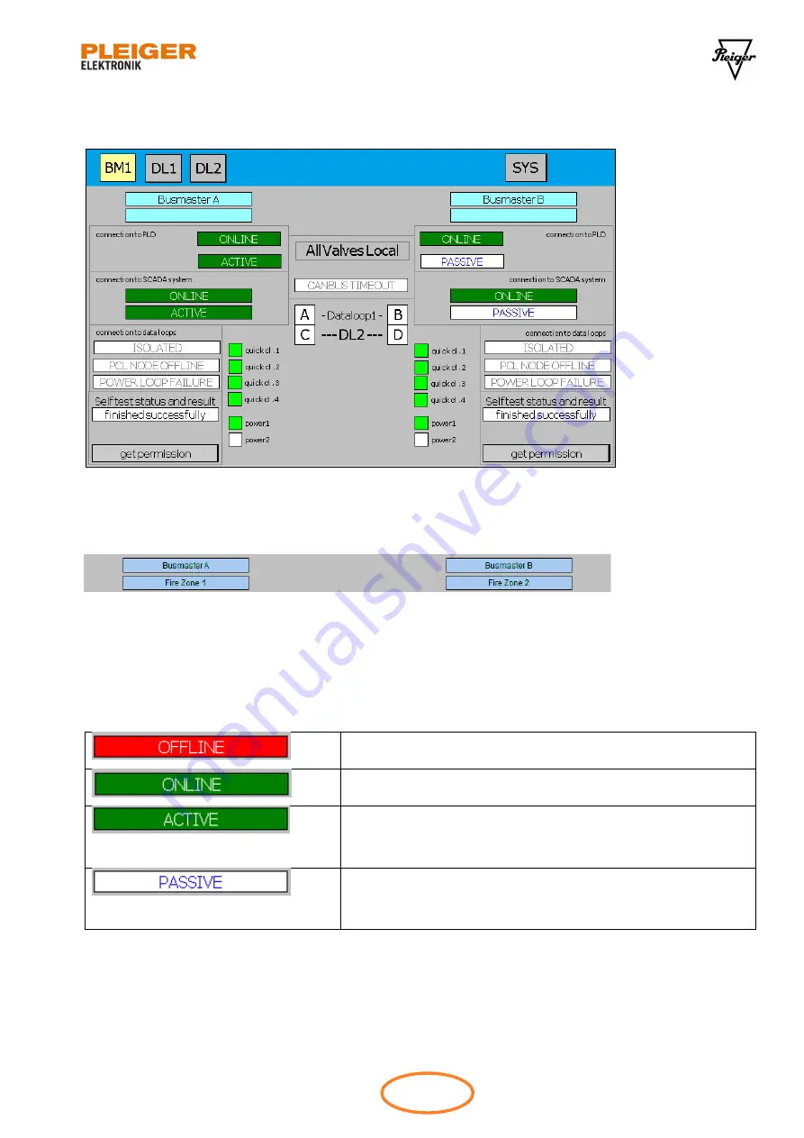
The state of the busmaster pair (busmaster A and busmaster B) is shown in the picture.
Figure 10-33: Busmaster page
A description for each busmaster is possible. Meaningful is the mounting place as the description.
For the visualization of the connections of the busmaster, the picture is divided into three rows.
•
Connection to PLD
•
Connection to SCADA system
•
Connection to data loops
10.4.1 Symbol explanation for the connection to SCADA system
The comunication between busmaster and SCADA is faulty.
The communication between busmaster and SCADA is OK.
Both busmasters can connect to the SCADA. One
busmaster will execute the commands from the SCADA.
This busmaster is active.
Both busmasters can connect to the SCADA. One
busmaster won’t execute the commands from the SCADA.
This busmaster is passive.
Table 10-2: Symbolization of the SCADA system connection states


