PCL
Pleiger Elektronik GmbH & Co. KG
www.pleigerelektronik.de
Fon +49 2324 398 333
22
/
65
Pleiger Control Loop
Manual version 2018-03
9
PCL-Master (busmaster)
9.1 General description
The busmaster serves as a communication gate-
way between the supervisory control system or
the local control system on the one hand and the
bus nodes on the other. The busmaster is based
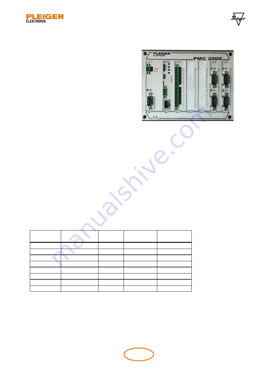
on the well proven hardware PMC2000 a compact
and modular control system with a robust stain-
less steel casing, a powerful 32 Bit micro control-
ler and a fast real-time operating system. Two
identical PMC2000 controllers are used to build a
redundant busmaster system. Each controller pro-
vides:
Power supply module
dc2 / dc3
isolated 18…32VDC input voltage,
isolated RS485 interface (used to connect a
supervisory control system (SCADA) via Modbus RTU, as Modbus RTU slave)
Processor board
mc3
with 32 bit processor, USB service interface 100Mbit/s Ethernet port, isolated CAN interface, uSD
card socket
up to 4 UART boards
si2
each equipped with 1 or 2 isolated RS485 interfaces (for data communication with VCI nodes)
I/O module
dea8
with 8 isolated digital inputs and 8 relay outputs
A redundant busmaster system comprises two masters A and B and the CAN bus connection.
Up to 8 data loops can be connected to such a busmaster system. Each data loop requires a RS485-
Interface on a si2 board on each side.
No. of the
data loop
Si2 board from
left to right
RS485
interface
Busmaster A
interface
Busmaster B
interface
1
1
lower
A
B
2
1
upper
C
D
3
2
lower
E
F
4
2
upper
G
H
5
3
lower
I
J
6
3
upper
K
L
7
4
lower
M
N
8
4
upper
O
P
Table 9-1: BusMaster data loop connection table
Figure 9-1: PCL busmaster with mc3


