76
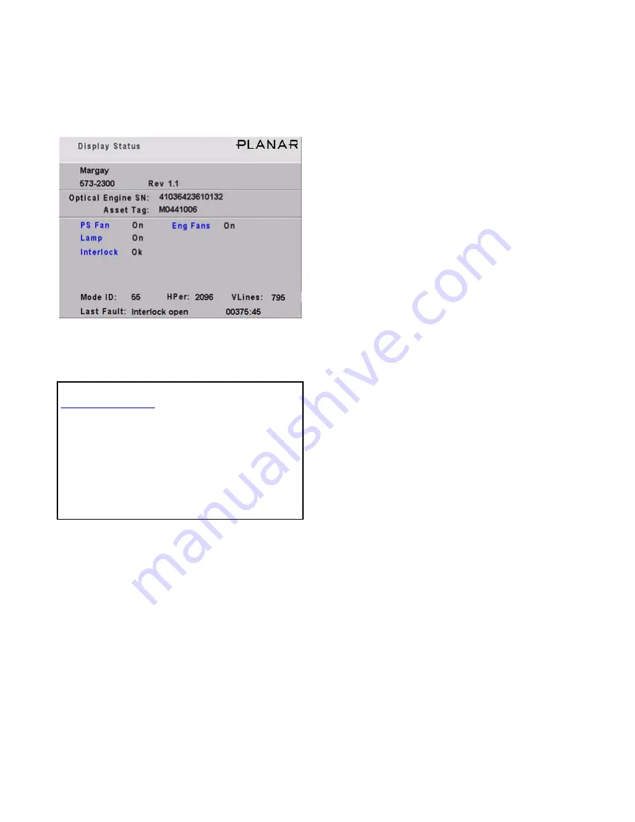
4.5 Asset Tag and Display Status
The Asset Tag feature allows you to identify each Margay by its serial number or in other ways.
To see the current Asset Tag, press
MONITOR
.
The Asset Tag is initially blank. You can write in
any short text message using RS232 commands. See
the Margay RS232 Guide, available from
Planar
’s
website.
Display Status menu information
• Margay—the name of this product
• 573-2300—the part number for the firmware in
Margays
• Rev—the revision number of the firmware cur-
rently operating in this Margay
• Optical Engine SN—the serial number read from
the optical engine in this Margay
• Asset Tag—a text line you enter (see above)
Planar
recommends you enter the serial number of this
Margay here, unless your facility has a special method of
identifying property.
• PS Fan and Eng Fans—If these fans are not on,
the lamp will not be on, and you wouldn’t be able
to see this menu at all.
• Lamp—same for this item.
• Interlock—If the interlock is Open, the lamp will
not light (unless the interlocks have been
bypassed to service the display).
• Mode ID—the number of the mode (type of sig-
nal) currently set
• HPer—the horizontal period in nanoseconds (ns)
of this signal (picture)
• VLines—the number of vertical lines in the pic-
ture
This number will be larger than the vertical resolution,
because it includes vertical blanking lines that are not visi-
ble.
• Last Fault—the last event that caused that forced
the lamp off, followed by the number of hours and
minutes since that happened, measured in Sys-
tem Hours, not clock time
Open
Planar
’s website in your internet browser.
In the top banner, click on LOGIN. This opens a
new window.
Click on the lower, blue LOGIN NOW button for
Consultants and Designers.
The User Name is tech.
The Password is help.
Click OK to open the window with all the manu-
als, utility programs, FRUs and firmware updates.
Summary of Contents for WN-5040-720
Page 1: ...WN 5040 720 User Guide...
Page 2: ......
Page 3: ...i WN 5040 720 Margay 50 Display Wall Unit User Guide 020 0548 00B 29 March 2007...
Page 6: ...iv...
Page 7: ......
Page 14: ...5...
Page 17: ...6...
Page 20: ...9...
Page 24: ...13...
Page 30: ...19...
Page 32: ...21 Electronics module as seen from the front The electronics module door is open...
Page 34: ...23 In Out...
Page 36: ...25...
Page 38: ...27 AC power in and out 1 4 5 3 2 6 No more than 4 115 VAC...
Page 40: ...29...
Page 51: ...40...
Page 54: ...43...
Page 56: ...45...
Page 58: ...47...
Page 66: ...55...
Page 70: ...59...
Page 72: ...61...
Page 74: ...63 ENTER ENTER...
Page 77: ...66...
Page 80: ...69...
Page 82: ...71...
Page 84: ...73...
Page 86: ...75...
Page 95: ...84...
Page 115: ...104 Diagnostics RS232 RS485 Status...
Page 116: ...105 Diagnostics Test Patterns...
Page 117: ...106 Diagnostics Setup Summary...
Page 128: ...117 Starts scanning the input con nectors for the next available source...
Page 131: ...120 7 3 Drawings All dimensions are in inches...
Page 132: ...121...
Page 133: ...122...
Page 134: ...123...
Page 140: ...129...
Page 144: ...133...


