71
3.8.3 Deleting a Configuration
There is no particular reason to delete a configuration, because you can always overwrite it.
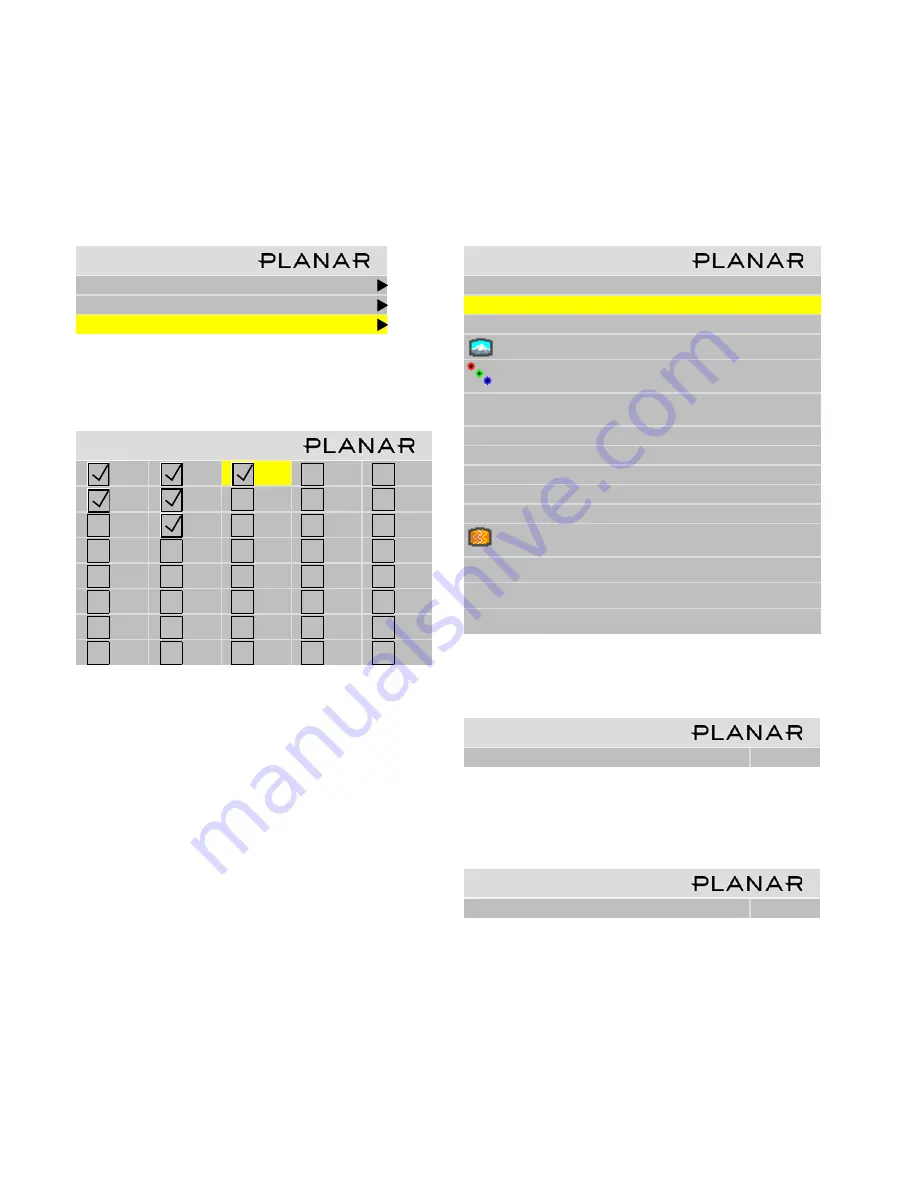
1. Go to the Memory menu (
Main > Memory).
2. Select
Delete
and press
ENTER
.
This opens a Delete grid of 40 numbered memory slots.
3. Navigate with the arrow keys to the slot you want to
delete and press
ENTER
.
When navigating, you can only go to the checked num-
bers. All the slots with check marks have something
stored in them. The others are grayed out.
✎
The menus you’ll see will likely have different
settings than those shown in the example below.
The Wall menu item appears only if Wall Mode is
enabled.
4. In the Delete detail menu
Delete Now
is selected.
5. Press
ENTER
.
1. Use the left arrow to make the Yes red and press
ENTER
.
✎
It is not necessary to delete the data in a memory
slot before saving new data. Saving will overwrite
the stored data. See “Saving Configurations” on
page 66.
M e m o r y
R e c a l l
S a v e
D e l e t e
D e l e t e
1
9
1 7
2 5
3 3
2
1 0
1 8
2 6
3 4
3
11
1 9
2 7
3 5
4
1 2
2 0
2 8
3 6
5
1 3
2 1
2 9
3 7
6
1 4
2 2
3 0
3 8
7
1 5
2 3
3 1
3 9
8
1 6
2 4
3 2
4 0
D e l e t e
S l o t t o D e l e t e
1 7
D e l e t e N o w
N a m e
A N 1 3 6 6 x 7 6 8
S o u r c e
A n a l o g
C o l o r s pa c e
R G B
R e s o l u t i o n
1 3 6 6 x 7 6 8
Wa l l
2 x 2
1 : 1
S c a l e / J u s t i f y
O n e t o O n e / C e n t e r
P o s t i o n / O v e r s c a n
1 6 8 , 1 9 / 0 %
Z o o m U L / L R
+ 0 , + 0
/ + 0 , + 0
Vi e w p o r t U L / L R
+ 0 , + 0 / + 0 , + 0
F r e q u e n c y / P h a s e
1 6 0 2 / 2 2 . 5 °
S h a r p n e s s
N o r m a l
B l a c k L e v e l
6 3
5 5
5 7
W h i t e L e v e l
1 6 6
1 7 0
1 6 9
C o n f i r m S l o t D e l e t e
A r e y o u S u r e ?
Ye s
N o
C o n f i r m S l o t D e l e t e
A r e y o u S u r e ?
Ye s
N o
Summary of Contents for Bay Cat X SN-4620-1080
Page 1: ...Bay Cat X SN 4620 1080 User Guide ...
Page 2: ...2 ...
Page 3: ...SN 4620 1080 Bay Cat X 46 Direct view LCD Panel User Guide 020 0571 00B ...
Page 5: ...Bay Cat X User Guide iii ...
Page 13: ...6 ...
Page 17: ...10 ...
Page 19: ...12 ...
Page 23: ...16 ...
Page 25: ...18 The Base Model shown above has only and Analog VGA connector The Video Model ...
Page 31: ...24 ...
Page 35: ...28 ...
Page 37: ...30 ...
Page 47: ...40 ...
Page 49: ...42 ...
Page 51: ...44 ...
Page 55: ...48 ...
Page 61: ...54 ...
Page 71: ...64 ...
Page 81: ...74 ...
Page 83: ...76 ...
Page 87: ...80 ...
Page 91: ...84 ...
Page 136: ...129 6 3 Drawings Dimensions in inches ...
Page 139: ...132 ...
Page 143: ...136 ...
Page 147: ...140 ...
Page 151: ...144 ...
Page 157: ...150 R J K O S T U V W X Y Z M Q N P R G I L F H B E C D A ...


