DA50S/DA55S/DA70S/DA75S AddressRight™ Printers Service Manual
6-5
Adjustments • 6
DA50S/DA55S (WS51/WS56) Adjustments
6.6 Exit Roller
Idler Assembly
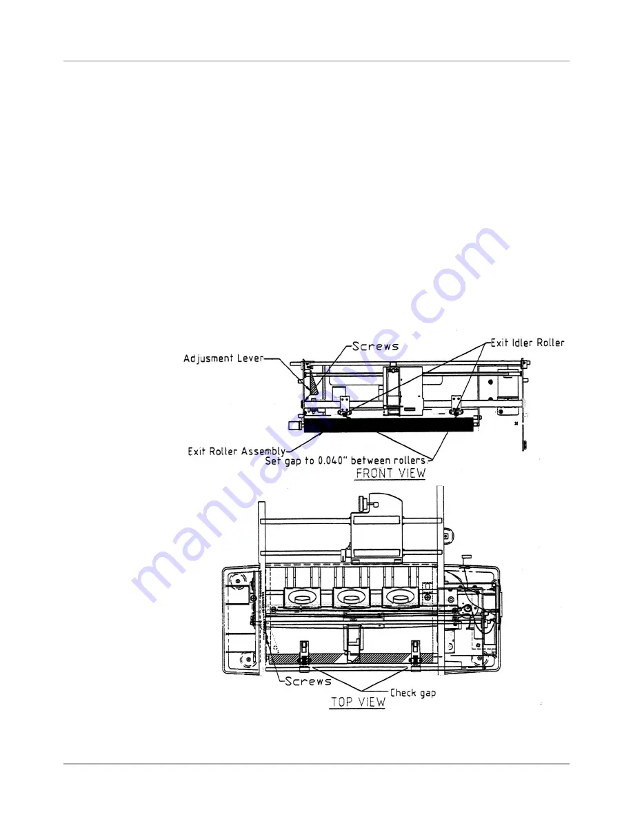
Figure 6-4 DA50S/DA55S Shuttle Mechanism
1. Raise the thickness adjustment lever to its highest point.
2. Check the gap between the exit roller assembly and the bottom of the
exit idler rollers. A 0.040” feeler gauge must pass freely between both
rollers. NOTE: Loosen the screws securing the adjustable roller assem-
bly on the right to raise or lower the right side of the exit roller assembly.
3. Check that the bar is pulled all the way forward and is level. NOTE: loos-
en screws to adjust bar when it is angled forward or backward.
4. Check the gap with a 0.065” feeler gauge. The gauge should not slide
between the rollers.
5. Secure screws once the gap is found.
6. Also check the gap between the small diameter rollers and the floor. The
gap should be between 0.1100” and 0.180”. Replace the non-conforming
exit slide roller if the gap is not between 0.100” and 0.180” and repeat
steps 1 to 6 again.


