background image

DA50S/DA55S/DA70S/DA75S AddressRight™ Printers Service Manual

5-5

Removal & Replacement • 5

DA50S/DA55S (WS51/WS56) Parts Removal

1.  Remove operator and non-operator side covers (see section 5.2).
2.  Remove main processor board/grounding sheet assembly (see section 

5.43A).

3.  On non-operator side, remove P18, P5, and P6 junction connectors.
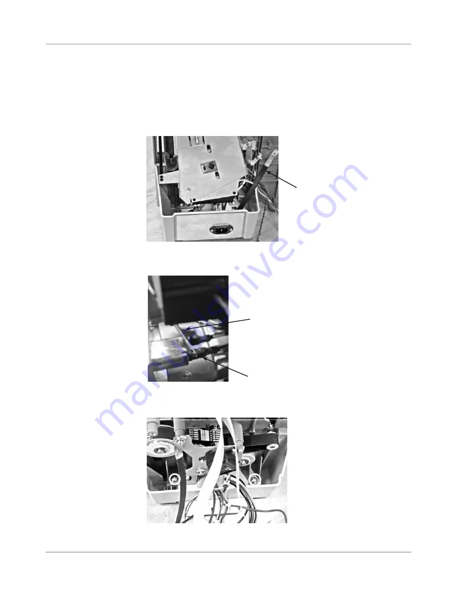
4.  Remove ground strap (furthest on the right with black sleeve), see photo.

5.  Remove three main power cables to AC inlet. Use screwdriver or needle 

nose pliers to pry off each (see photo below).

6.  Remove two phillips screws holding blue side chassis to bottom gray tray 

(see photo below). Do for both sides of machine (four screws total).

5.6  Power 
Supply 

Ground 
Strap

Side Chassis Attachment 
to  Gray Tray (screw loca-
tions in circles)

Using Screwdriver 
to Pry Cables from 
Spade Lugs (3)

Spade Lug

Summary of Contents for AddressRight DA50S

Page 1: ...Service Manual DA50S DA55S and DA70S DA75S AddressRight Shuttlehead Printers DA50S WS51 Black DA55S WS56 Black Color DA70S WS71 Black DA75S WS76 Black Color ...

Page 2: ...e Ca nadian Department of Communications Le present appareil numerique n emet pas de bruits radioelectriques depassant les limites appli cables aux appareils numeriques de la class A prescrites dans le Reglement sur le brouillage radio electrique edicte par le ministere des Communications du Canada NOTE This equipment has been tested and found to comply with the U S Standard for Safety UL1950 Thir...

Page 3: ...els 3 1 3 2 Printer Architecture 3 2 3 3 Operating Sequence 3 5 Chapter 4 Troubleshooting Diagnostics 4 1 Block Diagrams 4 1 4 2 Main Controller Board Diagnostics 4 3 4 3 Troubleshooting Tables 4 7 4 4 Printer Error Codes 4 14 4 5 Print Samples for Troubleshooting 4 15 Chapter 5 Removal Replacement 5 1 List of Procedures 5 1 DA50S DA55S WS51 WS56 Parts Removal 5 2 Covers 5 2 5 3 Display Keyboard 5...

Page 4: ... 5 19 Sensor 5 23 5 20 Shuttle Head Motor Print Head Shuttle Drive 5 24 5 21 H Block Tip 5 25 Chapter 6 Adjustments 6 1 List of Adjustments 6 1 Adjustments for All Models 6 2 LCD Display 6 2 6 3 Paper Sensor Test and Calibration 6 2 DA50S DA55S WS51 WS56 Adjustments 6 4 Main Brake 6 3 6 5 Printhead Clearance 6 5 6 6 Adjusting Exit Roller Idler Assembly 6 6 6 7 Printhead Drive Belt 6 7 6 8 Main Dri...

Page 5: ...2 LCD Main Menu A 4 A 3 LCD Setup Menu A 9 A 4 LCD Service Menu A 19 A 5 Setting Factory Defaults from LCD Menu A 24 A 6 Updating Firmware A 26 Appendix B Printer Communications B 1 Communication Scenarios B 1 B 2 Troubleshooting Tables B 4 B 3 Testing Printer Communications Within a Network B 7 Appendix C Schematics Main Processor Board Schematic C 2 LCD Keypad C 3 USB Ethernet LAN Function C 4 B...

Page 6: ...Table of Contents vi SV61831 Rev A DA50S DA55S DA70S DA75S AddressRight Printers Service Manual ...

Page 7: ...ers refer to these sources Software Control Panel Application on the host PC see the help sys tem on the software FAQs document see the Customer Service website under the product page for AddressRight printers Training see Enhanced AddressRight Shuttle Head Printers Self Direct ed Course GMS MC 03246 at My Portfolio on the Pitney Bowes intranet Training Job Aids print the job aids for the software...

Page 8: ...and methods before you install operate or repair the equipment to avoid personal injury or damage to the equipment If you train service people or equipment operators it is important to explain safety precautions to your students and encourage safety awareness 1 4 Safety Warning messages appear throughout this manual to alert you to potentially hazardous conditions Two designations indicate their r...

Page 9: ...ally dangerous A fuse is a weak link in a circuit designed to break down before anything else does The maximum safe current in a circuit is de termined by the designers Too large a fuse can pass excessive current damaging expensive equipment For electrical fires use Type C BC or ABC extinguishers only Don t use soda acid or other liquid stream extinguishers They will damage elec trical equipment a...

Page 10: ...cord Be careful of rugs even a few steps can recharge you Re ground your self whenever you ve walked away and returned to the machine Rugs are a major source of static buildup in the body Take greater precautions as the objects you handle get smaller A board in the machine is better protected than one that is not plugged in a chip on a board is better protected than one in your hand Stay away from...

Page 11: ...If the customer chooses to use another cable it must be no longer than 15 feet 5m For the Control Panel software the following is required Win2K SP4 WinXP Pro SP2 Win Server 2003 SP1 w latest Service Pack not yet tested on Vista Dot Net v1 1 5MB Disk space Administrative rights to install software Physical Dimensions DA50S DA55S 14 7 37 3 cm high 16 2 41 2 cm wide 21 7 55 1 cm deep without input g...

Page 12: ...ter 42 to 100 F 5 to 40 C Humidity Supplies 10 to 90 5 to 95 Maximum Wet Bulb Temperature 85 F 29 C Shipment Conditions Temperature Printer 40 to 140 F Humidity Supplies 5 to 100 Maximum Wet Bulb Temperature 85 F 29 C Noise Level DA50S DA55S The sound pressure level at the operator s position for this equipment as measured in any mode using ANSI and ISO Standards is less than 68 dB A DA70S DA75S T...

Page 13: ...right of the envelope normal printing orientation only not inverted Above the address block Below the address block Print Modes Print Resolution The printers each have three print resolutions They are Executive 600 Letter 300 and Draft 150 which represent the horizontal density Addi tionally there are two Light Mode settings ON and OFF which represent the vertical density When Light Mode is ON the...

Page 14: ...velopes for their customers invoices When the invoices are mailed back in their return envelope the USPS sorts and processes this mail according to what version of FIM barcode is used on the envelope FIM A Postage required POSTNET bar code included FIM C Postage prepaid POSTNET bar code included and FIM D Postage re quired POSTNET bar code not included One of the requirements of the FIM barcode is...

Page 15: ...ES All edges are viewed from the front surface of the material Two clear zones each 0 3 7 6mm wide are required on the piece of mail to allow clearance for the exit rollers Printing is allowed to the top edge of the media however print quality will be degraded The lower 5 8 16mm of the material is reserved for the lower right bar code when it is used Left Leading Edge Bottom Trailing Edge Top Feed...

Page 16: ...aim 10 WW Commercial Regular Horizontal within 1 5 mm Vertical within 1 5 mm Skew within 1 degree For other media Horizontal within 3 0 mm Vertical within 3 0 mm Skew within 2 1 2 degrees Recommended Usage The printers have been tested under many different conditions Use of the printer should fall within these piece usage recommendations Monthly Piece Usage Product Life Typical Maximum DA50S DA55S...

Page 17: ...ghput DA50S DA55S 10 000 letters per hour lph DA70S DA75S 14 000 letters per hour lph Based on Print quality Draft mode 3 line destination address 18 characters per line 12 point character size Time New Roman font Bidirectional printing of text NOTE Adding graphics and or printing at a higher resolution e g Letter or Executive mode will decrease throughput 2 2 Print Specifications 2 5 Material Spe...

Page 18: ... adhesive seal Postcards have no folds or bends The printable side may have a higher surface roughness than the non printable side Self mailers may be of C Z or half folded construction They may not exceed the maximum allowable thickness as specified on the previous page and must be tabbed per postal regulations A catalog may consist of multiple pages bound by adhesive or tabs on the feed edge or ...

Page 19: ...Envelope B4 353mm 250mm ENV_B5 Envelope B5 250mm 176mm ENV_B6 Envelope B6 176mm 125mm ENV_C4 Envelope C4 324mm 229mm ENV_C5 Envelope C5 229mm 162mm ENV_C6 Envelope C6 162mm 114mm ENV_C65 Envelope C65 229mm 114mm PG_ENV_C76 Envelope C76 162mm 81mm PG_ENV_C7 Envelope C7 114mm 81mm ENV_DL Envelope DL 220mm 110mm ENV_DLX Envelope DLX 235mm 120mm ENV_DLE Envelope DLE 225mm 114mm A4 A4 210mm 297mm A5 A5...

Page 20: ...2 10 SV61831 Rev A DA50S DA55S DA70S DA75S AddressRight Printers Service Manual 2 Specifications ...

Page 21: ... now stored on SDRAM Elimination of Centronics parallel and serial connectors replaced by USB and Ethernet board connectors Improved paper sensor calibration now accessible via LCD menu Keyboard LCD display changed on DA70S DA75S to match the former W660 W680 now DA50S DA55S 6 button style Added new second belt pass with spring loaded tensioner New options on the control panel menus for greater fl...

Page 22: ...d of the overall op erating system in the firmware that controls the behavior of the system and coordinates activities between the other sections User Interface The user interface is the LCD display the buttons and the software to drive it within the firmware Feeder and Transport Motion Control The feeder and transport motion control is responsible for feeding and positioning the envelope beneath ...

Page 23: ...ure Figure 3 2 Printer Block Diagram 0DLQ RQWUROOHU RDUG 6 RQWURO 3DQHO LVSOD RDUG 6 QWHUIDFH RDUG 6 8QLYHUVDO 3RZHU 6XSSO 6 0 0 0 6KXWWOH 0RWRU 7UDQVSRUW 0RWRU 0DLQWHQDQFH 0RWRU 3ULQW HDG ULYHU RDUG 6 6 3ULQW HDG DQ 3RZHU QSXW PLWWHU 6HQVRU 5HFHLYHU 6HQVRU 1 86 6KXWWOH 0RWRU QFRGHU 6KDIW QFRGHU ...

Page 24: ...ns 2 Eject Press to scroll through menu options from bottom to top When printer is off line press the minus key to eject an envelope 3 Menu Press to exit or enter a menu when printer is off line 4 Enter While in a menu press to enable an option 5 Cartridge Press to scroll through menu options from top to bottom When printer is off line press the plus key to bring the print head to the center of it...

Page 25: ...a the DA70S DA75S has a second set of transport rollers which help securely transport the printed media The feed roller moves the piece of media between the upper idler and the upper transport rollers The speed differential between upper lower trans port rollers and the main feed roller creates a gap between the moving piec es of media The lower transport rollers move the leading edge of the media...

Page 26: ...r the X Y cycle continues until the buffer is empty The piece of media is then fed between the right and left hand exit idler roll ers and the exit roller assembly The lower transport and exit rollers move the media until the trailing edge is past the infrared sensor path and ejects the media The sensor voltage changes and the processor registers the end of the media The feed rollers then push the...

Page 27: ...0DLQ RQWUROOHU RDUG 6 RQWURO 3DQHO LVSOD RDUG 6 QWHUIDFH RDUG 6 8QLYHUVDO 3RZHU 6XSSO 6 0 0 0 6KXWWOH 0RWRU 7UDQVSRUW 0RWRU 0DLQWHQDQFH 0RWRU 3ULQW HDG ULYHU RDUG 6 6 3ULQW HDG DQ 3RZHU QSXW PLWWHU 6HQVRU 5HFHLYHU 6HQVRU 1 86 6KXWWOH 0RWRU QFRGHU 6KDIW QFRGHU Figure 4 1 Shuttle Head Printer Block Diagram TIP See Appendix B Printer Communica tions for troubleshoot ing problems relating to networkin...

Page 28: ... 3RZHU VXSSO XVH LOLQ 3 6SDUWDQ VHULHV 6 34 6 67 0 2 5 0 0DLQ RDUG 6 K 6 ULGJH ULYHU 8 1 7UDQVSRUW 0RWRU UXVK 6 ULGJH ULYHU 6 5HJXODWLRQ IRU 9 9 9 9 9 86 XQFWLRQ 3KLOLSV 63 WKHUQHW 606 1 5 6 7 LUFXLWU 56 ULYHU WHVW RQO HH QFRGHU DW VKDIW 3 0 9 9 3 6ZLWFK 3 ULYHU Q 7U 3 3 ELW 7 ELW 7 3520 0 7 7 0 0 ELW DWD ELW DWD RQILJ 3LQ IRU DQG WKUX 3DSHU VHQVRU 5HG UHHQ 1 86 1 0DLQW 0RWRU 6WHSSHU 6 WR 0 LQ 38 ...

Page 29: ...sRight Printers Service Manual 4 3 Troubleshooting Diagnostics 4 Figure 4 3 Main Controller Board Mounted in DA50S DA55S Printers Figure 4 4 Main Controller Board Mounted in DA70S DA75S Printers 4 2 Main Controller Board Diagnostics ...

Page 30: ...ng printing or when stopped TP56 15V 5 Generated from main board voltage occurs when print heads are moving into maintenance station maintenance motor is running TP56 40V 5 Input from power supply TP55 16V 1 5V Generated from main board U20 for Transport Motor U20 pin 1 13V 1 5V Generated from main board U24 for Shuttle Motor U24 pin 9 Ground Ground for 3 3V measurement TP29 Ground Ground for 1 5V...

Page 31: ...dicates a board software problem CR10 Red Transport Motor Current Limit LED is lit from time to time when printer is printing LED stays lit in dicates shuttle motor over cur rent detected CR12 Green USB connection detected LED is lit when USB connection is detected blinks when USB is active LED stays off after connecting a USB device indicates a bad USB connec tion may be interface board in printe...

Page 32: ...AN J7 USB J13 Power J2 Transport Motor J11 Encoder on Shaft J23 Paper Sensor Receiver J18 Paper Sensor Emitter J3 Print Head Driver Board J22 LED for LAN J9 User Interface J5 Shuttle Motor J6 Maintenance Stepper Motor J4 Print Head Driver Board Fuse 1A Slo Blo 250VAC CR13 CR1 CR2 CR3 CR4 CR12 CR22 CR10 U24 Pin 9 Shuttle Motor U20 Pin 1 Transport Motor 4 2 Main Controller Board Diagnostics ...

Page 33: ...ators to thickness of material Loose encoder Make sure encoder is attached to printer properly Lead trail edge sensors dirty or bad Blow sensors with clean with air replace if necessary Fails to feed Feed gap incorrect Adjust H blocks to thickness of material Material out of spec Minimum thickness is 0 003 Maximum is 0 150 DA50 55S Maximum is 0 250 DA70 75S No staples paper clips etc on media Moto...

Page 34: ... or Paper jam Input bin empty Refill H Block separators improp erly adjusted Adjust to thickness of material Paper jam Paper path obstructed clear jam Damaged transport shaft encoder Replace the transport shaft encoder Shuttle jam Shuttle hitting material Adjust lever so head height is above media Print head shaft dirty Clean shaft with alcohol and soft cotton cloth Print head holder bushing clogg...

Page 35: ...e set screws two per pulley that are on the motor collar see photos below To gain access 1 On DA50S DA55S remove non operator access cover On DA70S DA75S open back plexigalss cover 2 From back of machine move maintenance capping station under motor on right towards front with a screw driver or other long object 3 Slide print head toward cen ter of machine 4 Locate and tighten set screws on metal c...

Page 36: ...er broken Check the print head holder for broken pins Replace print head drive board if pins are broken NOTE When trying to decide if print head driver board should be replace or not run Test Print Head from Setup Menu replace the ink cartridge with a new one then run the print head test again If the gaps are consistent with different ink cartridge then the print head driver board needs to be repl...

Page 37: ...ch ad dress setup Gray Print Ink Jet Cartridge empty Ink supply too low replace ink jet cartridge No Print Ink Jet Cartridge prob lems Purge ink jet cartridge Clean car tridge with soft cotton cloth and water Change to a known good cartridge Sensor dirty or bad Blow sensor clean recalibrate sen sor via Test Paper Sensor on Service Menu on LCD see section A 4 replace if necessary Power supply volta...

Page 38: ...he process Move the text or graphics that is close to the trail edge of the envelope up or down slightly so that the sensor is either covered or uncovered not half cov ered when the content is printed Address too low Software margin lead edge sensor seeing through paper The address is below the bottom edge of the material Increase the bottom edge margin Adjust lead edge sensor Paper size used does...

Page 39: ... board Replace the display board Nothing happens when power is switched on No power to AC inlet of printer Check power cord and AC outlet to which it is plugged in J13 on Main Board discon nected Connect J13 provides power to board from power supply Fuse is blown on Main Board Replace fuse Slo Blo 1A 250V on the mainboard right next to J13 Fuse blown in Power Sup ply Replace power supply no servic...

Page 40: ...inter back online Shuttle Jam 2 1 Clear jam and put the printer back online Over Current 2 2 Clear the jam and put the printer back online Detected as shuttle jam EEPROM Failure 3 Put the printer back on line to see if printer con tinues to run properly If not EEPROM hardware problem Service call File Print Error Not being displayed currently Eject Error Not being displayed currently Out of Memory...

Page 41: ...rinting problems you may encounter Sample Print What It Indicates Good printing Poor printing due to low ink replace ink cartridge Good test print Smudging need to purge print head A Skew B Misfiring head missing points do purge print head Table 4 8 Sample Prints Figure 4 6 Sample Envelope Printed with a Variety of Options All 3 versions of FIM Barcode USPS Postnet Barcode USPS Return Address ...

Page 42: ...4 16 SV61831 Rev A DA50S DA55S DA70S DA75S AddressRight Printers Service Manual 4 Troubleshooting Diagnostics ...

Page 43: ... each printer DA50S DA55S WS51 WS56 Parts Removal 5 2 Covers 5 2 5 3 Display Keyboard 5 3 5 4 Main Processor Board Grounding Sheet Assembly 5 3 5 5 USB Ethernet Input Board 5 4 5 6 Power Supply 5 5 5 7 Paper Transport Motor Belt 5 7 5 8 Sensor 5 9 5 9 Feed Roller Assembly 5 11 5 10 Encoder and Operator Side Drive Belt 5 13 DA70S DA75S WS71 WS76 Parts Removal 5 11 Covers 5 15 5 12 Display Keyboard ...

Page 44: ...to below Smoked output cover comes off with side cover Lift up printer slightly to completely remove side cover one printer foot is captured by the cover 3 Unfasten two phillips screws from operator side cover see left photo be low Lift up printer slightly to completely remove side cover two printer feet are captured by the cover Unfasten display keyboard cable gray P9 and the green grounding cabl...

Page 45: ...tom screws circled in right photo below to remove grounding sheet 1 Unfasten operator side cover two phillips screws Lift up printer slightly to completely remove cover two printer feet are captured by the cover 2 From behind cover unfasten display keyboard cable gray P9 and the green grounding cable see photo below 3 Carefully peel back display overlay from corner on front of display 4 Remove thr...

Page 46: ...al 5 Removal Replacement DA50S DA55S WS51 WS56 Parts Removal 1 Remove operator side cover see section 5 2 2 Remove P3 P4 P5 from USB Ethernet board 3 Remove two phillips screws fastening board to chassis 5 5 USB Ethernet Input Board USB Ethernet Board screw locations in circles ...

Page 47: ...P6 junction connectors 4 Remove ground strap furthest on the right with black sleeve see photo 5 Remove three main power cables to AC inlet Use screwdriver or needle nose pliers to pry off each see photo below 6 Remove two phillips screws holding blue side chassis to bottom gray tray see photo below Do for both sides of machine four screws total 5 6 Power Supply Ground Strap Side Chassis Attachmen...

Page 48: ...Removal 7 Lift and remove top chassis assembly from bottom gray tray photo 5 6 Power Supply continued 8 Remove the four screws holding captive the power supply feet Top Chassis Bottom Tray Power Supply Assembly 9 Remove power supply assembly includes fan housing and cables Close up of One Screw Holding Power Supply Feet in circle ...

Page 49: ...ectors 4 Remove ground strap furthest on the right with black sleeve see photo 5 7 Paper Transport Motor Belt 5 Remove three main power cables to AC inlet Use screwdriver or needle nose pliers to pry off from each spade lug see photo below 6 Remove two phillips screws holding blue side chassis to bottom gray tray see photo below Do for both sides of machine four screws total Ground Strap Using Scr...

Page 50: ... Parts Removal 8 Loosen main drive belt by idler pulley screw circled 7 Lift and remove top chassis assembly from bottom gray tray 9 Remove ground strap from motor force fit 10 Remove three screws that hold motor to side frame and remove motor 11 Remove belt 5 7 Paper Transport Motor Belt continued Top Chassis Bottom Tray ...

Page 51: ...e P18 P5 and P6 junction connectors 4 Remove ground strap furthest on the right with black sleeve see photo 5 Remove three main power cables to AC inlet Use screwdriver or needle nose pliers to pry off each see photo below 6 Remove two phillips screws holding blue side chassis to bottom gray tray see photo below Do for both sides of machine four screws total Ground Strap Side Chassis Attachment to...

Page 52: ...anual 5 Removal Replacement DA50S DA55S WS51 WS56 Parts Removal 8 Remove three tie wraps circled holding sensor harness P23 7 Lift and remove top chassis assembly from bottom gray tray 5 8 Sensor continued 9 Press sensor up and off holding tab circled Top Chassis Bottom Tray ...

Page 53: ...ide Remove four screws for u channel itself circled in photo below 5 9 Feed Roller Assembly 5 On non operator side remove P18 P5 and P6 junction connectors 6 Remove operator side drive belt off of feed roller assembly pulley Loos en idler pulley pointed to by screwdriver below Push idler pulley to compress the spring Retighten idler pulley Idler Pulley 4 Remove allen screws on black exit roller su...

Page 54: ...bly to chassis 12 Remove three phillips and one allen head screws holding deck to chas sis Remove grounding strap Remove deck 13 Separate blue side frames and remove feed roller assembly 10 On non operator side remove black brake allen and phillips screw pointed to by screwdriver below 5 9 Feed Roller Assembly continued 7 Slide belt off pulley 8 Remove e clip and nylon washer pointed to by screwdr...

Page 55: ... Remove allen wrench taped to operator side chassis 4 Turn encoder disc lock screw counter clockwise from two dot stop to one dot stop The screw recesses and exposes the hole where the allen wrench goes in on top Allen Wrench for Encoder Taped to Inside Chassis 5 Rotate the drive main drive belt which rotates the encoder This allows you to find the allen head screw that tightens the encorder on th...

Page 56: ...e main body cover of encoder from encoder mounting backing Do not remove backing plate because it is placed by the factory in a precise position 9 Release the belt tension by loosening the idler pulley then retighten Carefully Prying Off Encoder Body with Small Screwdriver NOTE When replacing place snap on new encoder on mounting back ing Tighten allen screw with wrench but do NOT overtighten Turn...

Page 57: ...uring removal and replacement 3 Remove four phillips head screws on non operator side cover note lock ing tabs on bottom 4 Remove three phillips screws on operator side cover one on either side one underneath Note the metal locating hooks behind cover Non Operator Side Cover Removed With Locking Tabs 5 Remove three phillips screws holding control panel cover two on one side one on the other 6 Remo...

Page 58: ...e and remove six allen screws 5 64 for bottom hatch cover 5 11 Covers continued 9 Remove six phillips screws for lower output cover two on each side two on face Remove one allen head recessed on side After Removal of Bottom Hatch Cover After Removal of Bottom Lower Input Cover After Removal of Lower Output Cover 10 Remove remaining allen head on operator side then two allen heads on non operator s...

Page 59: ...l board 3 Carefully peal back display overlay from corner 4 Remove three phillips head screws from underneath and remove board from cover 1 Remove non operator side cover 2 Remove all cables Starting clockwise from top right P22 P10 LAN P7 USB P13 P2 red white motor cable P5 P6 P11 P23 P18 P3 white ribbon cable P4 2nd white ribbon cable if color printer and P9 3 Remove three screws see photo below...

Page 60: ... cables to AC inlet Use screwdriver or needle nose pliers to pry off each see photo below 4 Remove four cables from spades on power switch next to AC inlet see photo below 5 15 Power Supply USB Ethernet Board screw locations in circles 5 Unfasten P13 from main board 6 Remove the four feet screws on bottom of power supply use stub by or 90 degree phillips 7 Remove power supply include fan housing a...

Page 61: ... 13 4 On operator side remove brake assembly circled in photo below by loosening two allen screws and removing one 5 16 Feed Roller Assembly Brake Assembly Removed 5 On operator side remove two allen screws for feed roller shaft bearing circled in photo Remove bearing Shaft and black rollers drop down 6 On non operator side loosen and remove feed belt drive idler circled in photo Then remove feed ...

Page 62: ...oval Replacement DA70S DA75S WS71 WS76 Parts Removal 7 On non operator side remove two allen and two phillips screws for metal bracket holding feed roll drive belt 8 On non operator side pull out feed roller assembly through access hole Phillips Allen 5 16 Feed Roller Assembly continued ...

Page 63: ... and Main Motor Main Drive Idler 4 Remove large metal pulley see photo below and nylon washer used for motor drive belt 5 16 allen used Remove motor drive belt Large Metal Pulley and Motor Drive Belt Motor Drive Belt Plate 6 Remove four allen screws circled in photo below holding motor to motor drive plate 7 Remove input side lower cover 8 Back out motor through opening in input side 5 Remove six ...

Page 64: ...emoval 5 17 Motor Drive Belts and Main Motor continued 9 Disconnect encoder harness ENC at motor and J2 from main board and remove main motor 10 Remove e clip and wave washer from inside side frame holding the jack shaft to frame 11 Unplug cable to encoder ENC 12 Remove main drive belt see photo above Encoder Cable Main Drive Belt ...

Page 65: ... drive belt by loosening the idler Unattach belt 5 18 Exit Roller 1 Tip machine on side and remove bottom hatch cover 2 Slide sensor circled in photo below off holding tab 5 19 Sensor 3 Remove J23 harness to Main Board Removal of Exit Roller 4 Remove operator side frame screws five allens and two phillips see above 5 Spread side frames apart and remove exit roller from non operator side frame Note...

Page 66: ... nylon washer circled below holding u channel 5 20 Shuttle Head Motor Print Head Board Shuttle Head Drive Belt 5 Remove print head motor and print head board as necessary from u channel assembly U Channel Assembly Print Head Board Print Head Motor Print Head 3 Unfasten J3 and J4 flat gray cables J18 sensor harness J5 motor har ness and J6 from main board 4 Slide out u channel assembly from non ope...

Page 67: ...cement 5 DA70S DA75S WS71 WS76 Parts Removal 1 Slide metal guide and paper stand away from H block 2 Remove allen screw see photo below circled holding H block and re move H block 5 21 H Block Tip 3 On backside of H block remove phillip screws see photo below circled for each tip ...

Page 68: ...5 26 SV61831 Rev A DA50S DA55S DA70S DA75S AddressRight Printers Service Manual 5 Removal Replacement DA70S DA75S WS71 WS76 Parts Removal ...

Page 69: ...CD Display 6 2 6 3 Paper Sensor Test and Calibration 6 2 DA50S DA55S WS51 WS56 Adjustments 6 4 Main Brake 6 3 6 5 Print head Clearance 6 5 6 6 Adjusting Exit Roller Idler Assembly 6 6 6 7 Print head Drive Belt 6 7 6 8 Main Drive Belt 6 8 6 9 Adjusting Service Station Assembly 6 9 DA70S DA75S WS71 WS76 Adjustments 6 10 Main Brake 6 10 6 11 Print Head Drive Belt 6 10 6 12 Timing Belt 6 11 6 13 Main ...

Page 70: ...ice Menu 3 Raise the Print Station U Channel Assembly to fully open with the sensor path clear then do the following Run the calibration by pressing Enter on the panel If the calibration fails then A Verify cable connections at sensor and at board B Verify that the sensor is not blocked C Clean the sensor for dirt and dust If the calibration still fails a Replace the sensor and retry calibration b...

Page 71: ...driver and a feeler gauge to adjust the brake gap to 0 100 0 020 about 3 32 between the two legs as shown below If stream feeding occurs after you set the proper gap replace the brake as sembly see Chapter 5 for instructions 6 4 Main Brake Figure 6 2 Brake Assembly Measure here HERE EASURE 2EAR 3UPPORT 0LATE SSEMBLY Adjustment Screw ...

Page 72: ...edia thickness lever all the way down 4 Insert a 0 040 feeler gage between the bottom of the print head and the floor of the printer CAUTION Use care when using the gage You can easily damage the print head 5 Check for proper clearance The tolerance is 0 010 A 0 035 gage should fit between the print head and the floor a 0 045 gage should not 6 To adjust A Loosen the set screw on the media thicknes...

Page 73: ...crews securing the adjustable roller assem bly on the right to raise or lower the right side of the exit roller assembly 3 Check that the bar is pulled all the way forward and is level NOTE loos en screws to adjust bar when it is angled forward or backward 4 Check the gap with a 0 065 feeler gauge The gauge should not slide between the rollers 5 Secure screws once the gap is found 6 Also check the...

Page 74: ...is mounted on an adjustable bracket as shown at the right To adjust belt tension 1 Remove rear cover and shuttle driver board 2 Move the print head holder to the park position 3 Loosen two bracket mounting screws See Figure 6 4 4 Adjust the bracket until no further movement is available and then tighten Figure 6 5 DA50S DA55S Print Head Drive Belt Adjustment Bracket Mounting Screws ...

Page 75: ... 1A 2 Remove main processor board grounding sheet assembly see section 5 3A 3 Loosen the shoulder screw on the pulley assembly adjustable pulley see figure below NOTE DO NOT turn this screw all the way out 4 The compression tensioner will set the proper tension for the belt Tight en the slotted shaft to secure the pulley in place 6 8 Main Drive Belt Figure 6 6 DA50S DA55S Main Drive Belt Adjustmen...

Page 76: ...on the sled 3 Cycle the Sled Cover on the Service Station Assembly back and forth to make sure the seals cover the ink cartridges 4 With the rack all the way in its forward position Raise the front and rear of the Service Station as required to seal both heads The gap between the top of the Service Station Sled Cover and the bottom of the ink car tridge should be around 0 180 Tighten both screws t...

Page 77: ...5S DA70S DA75S AddressRight Printers Service Manual 6 9 Adjustments 6 DA50S DA55S WS51 WS56 Adjustments Figure 6 8 DA50S DA55S Service Station Assembly Adjustment Post Sled 6 9 Service Station Assembly continued ...

Page 78: ...ent Brake Assembly Screws for Tensioner Measure Gap Here The Print Head Drive Belt tension is set with the adjustable pulley assembly Use a Force Dial Gauge with an L shaped hook when resetting the tension 1 Move the print head holder to the park position 2 Loosen the adjustable pulley assembly DO NOT FULLY UNDO 3 With the Force Dial Gauge pull on middle of the rear of the Print Head Drive Belt to...

Page 79: ...et utilizing the adjustable pulley assembly The tension is automatically set by the springs pressing up on the adjustable pulley assembly NOTE To check the belt tension use a Force Dial Gauge with a L shaped hook Pull on the belt at the midpoint of the longest span between two pul leys With the Force Dial Gauge pull until a measure of 2 75 pounds of force 4 oz is obtained when the belt is deflecte...

Page 80: ... Service Station wipers against the Print Heads to prevent drying and clogging of the ink jets The alignment must be such that during movement of the Service Station Sled its finger does not miss and locks with the protruding tip on the Print Head Holder Realignment will be necessary if the Service Station or the Print Head Holder is removed or if over a period of time the set screw becomes loose ...

Page 81: ...ntacting rubber or plastic parts The use of anything but alcohol will cause premature breakdown of the rubber compound General Follow these standard procedures when performing preventive maintenance 1 Ask the operator to report any problems If problems were noted try to determine if they were due to operator error out of spec materials or a machine fault 2 Print several test sheets to evaluate pri...

Page 82: ...th or paper tower Monthly or as Needed Paper Sensor With use a dusty film builds up on the sensor This can even tually cause misfeeds Use compressed air to blow dust from the sensor If a film has developed over the sensor remove the sensor and clean it with alcohol See Chapter 5 of this manual for removal in structions Weekly Print Head The print head periodically performs a self cleaning cycle If...

Page 83: ...the customer s PC communicat ing with the printer Levels of Access Determined by which control panel buttons are pushed in what order Determined by logon password Standard no password Supervisor 55555 password Service 32322 password Menus Functions Main Menu Setup Menu Service Menu Setting Factory Defaults Updating Firmware Status tab Job Control tab Alignment tab Configuration tab Test Adjust tab...

Page 84: ...omer applications you will use the soft ware control panel application on the host PC to configure the printer For more information on this ap plication see its built in help Main Screen of Control Panel Software Option on Host PC Feature Tab Access on Control Panel Software by Online Offline State of Printer State Status Tab Job Control Tab Alignment Tab Configuration Tab Test Adjust Tab Preferen...

Page 85: ...d by the Windows ap plication sending the print job to the printer TIP LCD printer control panel menus can only be accessed when the printer is in the offline mode Accessing the LCD Menus Press On Line The LCD displays OFF LINE and the green light goes out For Main Menu press Menu For Setup Menu press and hold Menu for four seconds For Service Menu press Eject first then while holding it down pres...

Page 86: ...batch b Get Addr inter c Clear Memory 6 Clear Counter 7 Job Settings a Load b Save 8 Image Overlay a Capture Overlay b Clear Overlay c Print Overlay TIP Virtually all of the settings in the printer control main menu are overruled by the Windows application sending the print job to the printer TIP Press Eject or Cartridge to scroll through the submenus within a menu or the settings within a menu su...

Page 87: ...e between the top edge of the media and first line of the ad dress C Line Spacing Automatic 3 4 5 6 8 lines inch Whenever scalable fonts are used automatic line spacing is recommended Automatic line pitch selection is based on industry standard definitions for line spacing for each print pitch and style selected The printer automatically selects the correct setting for the font and size of the cha...

Page 88: ...ing NOTE When A Name displays and Test Env is pressed all the installed fonts names are printed using their font characters along with their Typeface IDs using Courier NOTE When the name of the font displays Courier Times New Roman etc and Test Env is pressed all the characters used in the currently selected symbol set are printed 16 characters to a row from code 0x20 to code 0xFF in 12 point font...

Page 89: ...on line printing resumes at the recovered page B Get Addr inter Scrolling of addresses to select from Allows you to retrieve any address in the data buffer using an alternate method The last address printed N is reprinted when the key is pressed If the key is pressed again the N 1 address is reprinted and so on until the recovery buffer is exhausted When the printer goes back on line printing resu...

Page 90: ... printer setup when changing print jobs Submenu Option Settings What It Does A Capture Overlay Yes No When YES is selected the printer is set to use the next page received from the host computer as an overlay The Next page will be used as overlay message is displayed for two seconds and you return to Image Over lay sub menu If NO is selected you return to Image Overlay sub menu B Clear Overlay Yes...

Page 91: ...e Setup Menu Press On Line The LCD displays OFF LINE and the green light goes out Press and hold Menu for two seconds TIP Virtually all of the settings in the printer control setup menu are overruled by the Windows application sending the print job to the printer TIP Press Eject or Cartridge to scroll through the submenus within a menu or the settings within a menu submenu option Press Enter to se...

Page 92: ...purging or cleaning the printhead doesn t work then try a new ink cartridge Menu Option Settings What It Does Purge Print Head Yes No Allows you to purge the print head which may clear clogged ink from the print nozzles Often this returns print quality to a satisfac tory level When prompted to run press Enter and the printer displays Please wait Ink jets being purged 3 Purge Print Head Menu Option...

Page 93: ...sed and held for at least two seconds the printer increments or decrements the value by 10 Pressing Menu saves sets the entire address and exits the TCP IP submenu B IP Address 000 000 000 00 000 to 255 for each address segment C Subnet Mask 000 000 000 000 000 to 255 for each address segment D Gateway Address 000 000 000 000 000 to 255 for each address segment E Port Number 5100 default Allows yo...

Page 94: ...ter in the address Each HEX code is two digits long separated by brackets A capital letter A is a Hex 41 When reviewing addresses printed in HEX mode start from the end of the address at the ZIP Code remember 30 s are the numbers and count backwards toward the beginning of the address Count the number of carriage returns CR 0D and line feeds LF 0A Check that the printer s address setup has the sam...

Page 95: ...1 0 1 2 3 4 5 6 7 8 9 A B C D E F NUL SOH STX ETX EOT ENQ ACK BEL BS NT LF VT FF CR SO SI DLE DC1 DC2 DC3 DC4 NAK SYN ETB CAN EM SUB ESC FS GS RS US SP 0 1 2 3 4 5 6 7 8 9 A B C D E F G H I J K L M N O P Q R S T U V W X Y Z _ a b c d e f g h i j k l m n o p q r s t u v w x y z DEL 0 1 2 3 4 5 6 7 8 9 10 11 12 13 14 15 0 1 2 3 4 5 6 7 0 16 32 48 64 80 96 112 D E C H E X LSB MSB A 4 LCD Setup Menu Y...

Page 96: ...ational Standards Orga nization ISO character set based on the needs of the print job B Inch Millimeter Inch Millimeter Allows you to select the printer measurement system either inch or millimeter C Menu Languages English German French Italian Spanish Dutch Polish Japanese Allows you to translate the information displayed on the LCD to the language selected Menu Option Settings What It Does Envel...

Page 97: ...en the ejection of the blank envelope if Auto Eject mode is On and the start of next batch job Menu Option Settings What It Does ROM Revision ROM REV xx xx xx MAIN COUNT xxxxxx Allows you to verify the firmware revision installed in the printer e g for CASS certi fication It is also useful to determine if the printer requires an upgrade The maintenance count which is the total number of print cycl...

Page 98: ...ing when a bundle break is detected 11 Print Head Maintenance Submenu Option Settings What It Does A Head Mainte nance Enabled Disabled Allows you to enable and disable the per formance of print head maintenance cycles during print jobs The maintenance cycle consists of moving the print heads to the maintenance station firing all the nozzles on the ink cartridges into an ink reservoir and then wip...

Page 99: ...ess After Address Allows you to specify whether to print the break characters before or after the address F Print Break Characters Enabled Disabled Allows you to specify whether to print or not print the break characters G Break Pause Time 0 to 30 00 seconds in 0 25 second increments Allows you to specify the length of time the printer will pause printing when a tray break is detected 14 Low Ink W...

Page 100: ...ine hard ware or software or actions by the machine that are responses to user actions Errors are events that are caused by exceptions or conditions that cause the printer to stop prematurely or unexpectedly B Logging Level Standard Verbose When the logging option is set to Standard the system will log user and error events where the record in the log includes the event or error ID the clock tick ...

Page 101: ... line address of A s The left edge of line two does not align with line one or three EXAMPLE AAAA AAAA AAAA If the left edge of the address needs left jus tification print out a left justify test pattern by pressing Test Env The printer prints the following test pattern EXAMPLE 2 3 4 5 6 7 8 9 1 0 The Left Justify test pattern consists of four rows Each row has a series of ten vertical lines Selec...

Page 102: ...ght into the hole to the bottom sensor A Sensor Unblocked message indicates the upper sensor isn t operating Calibrate Sensor Allows you to calibrate the paper sensor 1 The system displays Clear Sensors when the Calibrate Sensor menu item is selected When displayed press Enter 2 At the Raise paper guide prompt press Enter The system automatically calibrates the paper sensor During the calibration ...

Page 103: ...oes Test Paper Motor Allows you to test the feeding mechanisms of the printer by controlling the transport mo tor The printer feeds and transports paper through the printer in two ways in a small amount 1 150 inch by pressing or in a large amount 1 inch by pressing Menu Option Settings What It Does Test Display Allows you to determine if the LCD display is functioning properly is missing character...

Page 104: ...o the bottom edge of the bar code 1 16 inch Press MORE or LESS to adjust the barcode bottom edge distance by increasing or decreasing the number 0 50 A lower number moves the barcode down a higher number moves the barcode up toward the top of the envelope NOTE If the barcode position is fluctuat ing check the tension of the main drive belt See Chapter 6 Adjustments for adjustment procedures Press ...

Page 105: ...Env The printer prints a row of ten columns shown right Each of the ten col umns in the test pattern must be a straight vertical line When the lines in the test pattern look broken compare the pattern to the top two example patterns 2 Select the one that best matches the test pattern and perform the adjustment on the print head as noted 7 Print Head Skew Submenu Option Settings What It Does Brand ...

Page 106: ...he printer settings are not reset The Restarting Printer message is displayed Resetting printer Please wait Displayed while the printer is being reset to factory defaults Memory reset Restarting printer Displayed for three seconds when printer settings have been reset to fac tory defaults Restarting printer Displayed for three seconds when user chooses not to reset the printer to factory defaults ...

Page 107: ...I Measurement Units Inch Menu Language English Envelope Feed Delay 0 0 Auto Eject Off Eject Delay 5 0 Head Maintenance Enable Cycle Time 2 minutes Bundle Break Disable Bundle Break Character Bundle Break Char Count 6 Character Orientation Vertical Break Location After Address Print Break Characters Disabled Break Pause Time 0 00 seconds Tray Break Disable Break Character Break Character Count 6 Ch...

Page 108: ...n tab 5 Click Log In Enter 32322 and click OK NOTE You can use the Supervisor password 55555 to log in but it will not give you access to the Service tab 6 The buttons in the Supervisor Commands pane become active Go to that appropriate section below To Update Firmware A Click Update Printer Firmware B Insert the media CD USB stick or floppy drive containing the printer firmware into the host comp...

Page 109: ...ce xxxxxxx the printer name such as ADRPTR47B069 Record this Device name xxxxx 4 Press Menu button several times to back out of the Setup menu and go into the Offline mode 5 If the network doesn t have a DHCP server please obtain a static IP Address with a Subnet Mask and Gateway IP Address for each printer Enter this data into the printer by going to the Communication option 5 under the Setup Men...

Page 110: ...to memory Verifying Update Bytes left xxxxxxxxx displayed while a data integrity check is performed on the update Update Complete Restarting printer displayed when the download is complete is the printer is rebooted A 7 Updating Firmware 10 Close Internet Explorer 11 Restart the printer 12 Take the printer OFFLINE 13 Enter the Setup Menu and go to option 10 ROM Revision 14 Verify ROM Version has b...

Page 111: ...ntrol panel or Control Panel Software on the host PC LCD Control Panel Navigate to the Service Menu and perform the following four mainte nance procedures see Section A 5 for more information if necessary Test Paper Sensor Left Justify Envelope Bottom Edge Print Head Skew Control Panel Software on Host PC A Double click on the Pitney Bowes Control Panel icon The Addressing Printer Control Panel di...

Page 112: ...A 30 SV61831 Rev A DA50S DA55S DA70S DA75S AddressRight Printers Service Manual Appendix A Printer Control Panel Menus and Utilities ...

Page 113: ...f printer is normally used in a network en vironment B USB Print Sharing PC has Windows print sharing ON and printer is shared on a net work printer con nection via USB port Allows multiple PCs to print to it Computer DAxxS Ethernet Cable NIC Port USB Port Computer NIC Port USB Port C Network Static IP Address Printer is set up as printer on the network with a static IP Address via a router on the...

Page 114: ...ver If Customer IT depart ment would prefer DHCP and name reso lution enable DHCP on the printer to obtain an IP address from the DHCP server On the print drivers ports tab configure port Printer name or IP ad dress must use printer name where X is the unique information from each printer as in ADRPTRXXXXX See Figures B 1 and B 2 on next page E Direct Connect via Cross over Cable Printer set up as...

Page 115: ...Manual B 3 Printer Communications Appendix B Figure B 1 Typical Printer Port Settings When Using Name Resolution Communications Figure B 2 Typical Configuration Screen of Printer Port Settings for Name Resolution Communications B 1 Communication Scenarios ...

Page 116: ...d right click on our printer Select Printer Properties Advanced and verify proper communications settings Cable connections Check USB or network Ethernet cable Make sure cable is con nected securely at both ends Does USB cable exceed maximum 15 for USB connection Replace cable with known good cable Is a non powered hub used to extend these distances Remove from hub Bad memory in printer Turn print...

Page 117: ...r to stop printing Ethernet port con nected to printer not activated Have customer s IT department check to make sure port is activate If it is check TCP IP settings at host PC see cell above Communication set tings not set correctly within LCD menu Verify proper settings on printer in Setup Menu 5 Communications see section A 3 against customer s requirements Under TCP IP setting or DHCP confirm ...

Page 118: ...ot printing continued Bad USB Ethernet Interface board Plug external Ethernet or USB cable directly to the connector on the main board to verify whether you have an inoperative internal cable or connec tor on the back of the printer Bad Main Board Troubleshoot main board see sec tion 4 2 to determine if it is bad replace if necessary B 2 Troubleshooting Tables ...

Page 119: ...f you don t have any of these values you might have a problem with the DHCP server distributing this data to the printer or the printer isn t retaining these values For example if the printer s IP address is 0 00 00 0 then the printer isn t receiving a IP address from the DHCP Server The DHCP server might also have a problem resolving the device name You can create a new TCP IP port utilizing the ...

Page 120: ...ter retrieved a DCHP address If DHCP is disabled pressing Enter saves the current address element and moves to the next address elements The system blinks the segment that is currently selected When the or keys are pressed and held for less than two seconds the printer increments or decrements the values of the selected segment by 1 When the or keys are pressed and held for at least two seconds th...

Page 121: ...tics DA50S DA55S DA70S DA75S AddressRight Printers Service Manual C 1 List of Schematics Main Processor Board Schematic C 2 LCD Keypad C 3 USB Ethernet LAN Function C 4 Black White Printer Head C 5 Color Print Head C 6 ...

Page 122: ... 4 T3 E 3 P19 R19 T 1 9 P20 R20 T 2 0 B 8 A 8 B 9 A 9 A 1 8 D 1 9 D1 C 1 7 D 1 8 E 1 9 E 2 0 A 1 C 2 D 4 B 6 A 7 B 7 A 6 N20 N19 M20 M19 F19 F20 F17 F18 D16 D17 C16 B17 A17 G20 G19 H17 H18 P 2 F 2 G 2 H 2 J2 K 2 L 2 M 2 N 2 F 1 G 1 H 1 J 1 K 1 L 1 M 1 N 1 R 1 P 1 R 2 T 1 T 2 D 5 B10 C 1 K 2 0 J 1 9 J 2 0 H 1 9 H 2 0 B 1 A15 B16 A16 B11 B14 B15 B13 B12 A10 A13 A14 A12 A11 A 5 C 5 B 5 D 2 C 6 D 3 D6...

Page 123: ...G HOLE LCD2 MOUNTING HOLE LCD3 MOUNTING HOLE LCD4 MOUNTING HOLE KP1 MOUNTING HOLE KP2 MOUNTING HOLE KP3 MOUNTING HOLE KP4 MOUNTING HOLE KP5 MOUNTING HOLE KP6 MOUNTING HOLE KP7 J2 1 J2 2 J2 3 J2 4 J2 5 J2 6 J2 7 J2 8 J2 9 J2 10 J2 11 J2 12 J2 13 J2 14 WS92002 2 24 06 2 24 06 CO10343 JOG YOUNG LEE WS CONFIGURATION CONTROL DOCUMENT REQUIRES UPDATING WHENEVER THIS DOCUMENT IS REVISED WSXX REF CCWS8200...

Page 124: ...8 7 6 5 4 3 2 1 261 3449 1 4 2 3 5 6 7 8 9 10 11 12 13 14 15 16 YEL GRN 4 7uF C2 0 1uF C1 4 261 3017 1 J3 2 3 4 5 6 J5 1 2 3 WS92009 2 24 06 2 24 06 CO10343 YOUNG LEE JOG WSX NOTES 1 UNLESS OTHERWISE SPECIFIED ALL RESISTORS ARE IN OHMS 5 AND 1 10 WATT ALL CAPACITANCE VALUES ARE IN MICROFARADS uF 2 FOR ASSEMBLY DRAWING SEE WS82009 REF CCWS82009 WSXX LAYOUT NOTES 1 BOARD IS TWO LAYER 2 ALL TRACES SH...

Page 125: ...3 OUT_2 SERIAL_DATA_IN LOGIC_SUPPLY 5 OUT_23 OUT_24 OUT_18 NC_1 OUT_19 GND BLNK OUT_17 OUT_20 OUT_22 OUT_21 C3 0 1uF C4 0 1uF C5 0 1uF C6 0 1uF LH2 MTG HOLE MH3 MTG HOLE MH2 MTG HOLE MH1 MTG HOLE LH1 MTG HOLE 2 4 3 1 HEDS_9721 200 1080 U1 VCC CHANNEL_A GND CHANNEL_B R8 4 7Kohms R7 4 7Kohms C2 293 3104 0 1uF 284 4689 C1 4 7uF 16V 297 9477 C7A 470uF 10 16V C7B 297 9477 470uF 10 16V C7C 297 9477 470u...

Page 126: ...OUT_1 OUT_3 OUT_2 SERIAL_DATA_IN LOGIC_SUPPLY 5 OUT_23 OUT_24 OUT_18 NC_1 OUT_19 GND BLNK OUT_17 OUT_20 OUT_22 OUT_21 0 1uF C3 0 1uF C4 0 1uF C5 0 1uF C6 MTG HOLE LH2 MTG HOLE MH3 MTG HOLE MH2 MTG HOLE MH1 MTG HOLE LH1 2 4 3 1 HEDS_9721 200 1080 U1 VCC CHANNEL_A GND CHANNEL_B 4 7Kohms R8 4 7Kohms R7 0 1uF C2 293 3104 16V 4 7uF 284 4689 C1 470uF 10 16V 297 9477 C7A 470uF 10 16V C7B 297 9477 470uF 1...

Page 127: ...1 Elmcroft Road Stamford Connecticut 06926 0700 www pb com Printed on recyclable paper PB Form SV61831 Rev A 3 07 2007 Pitney Bowes Inc All Rights Reserved Printed in the USA sv61831reva ...

Reviews: