DA50S/DA55S/DA70S/DA75S AddressRight™ Printers Service Manual
5-15
Removal & Replacement • 5
DA70S/DA75S (WS71/WS76) Parts Removal
5.11 Covers
1. Slide off side guide (metal) and unscrew threaded knob for paper stand
(chrome). Slide chrome stand to right and lift out.
2. Remove four allen screws (5/64”) on rear and remove smoked output
cover. NOTE: Hinges for smoked cover are spring-loaded, so be careful
during removal and replacement.
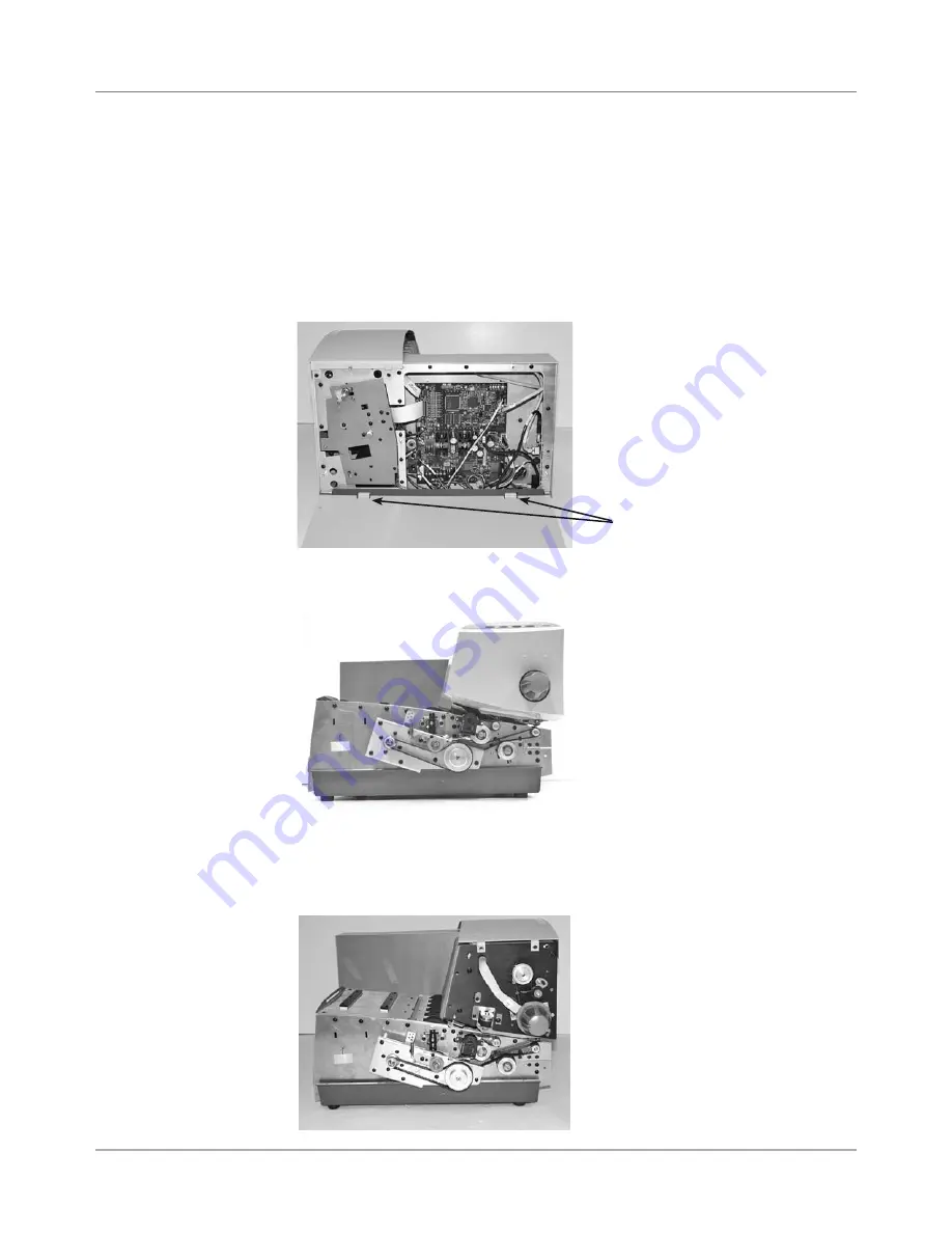
3. Remove four phillips head screws on non-operator side cover (note lock-
ing tabs on bottom).
4. Remove three phillips screws on operator side cover (one on either side,
one underneath). Note the metal locating hooks behind cover.
Non-Operator
Side Cover
Removed With
Locking Tabs
5. Remove three phillips screws holding control panel cover (two on one
side, one on the other).
6. Remove gray P2 and green ground cable (uses 9/64” allen) going to key-
board/control board and remove cover.
After Removal
of Operator
Side Bottom
Cover
After Removal
of Operator
Control Panel
Cover


