PDP-425CMX
183
5
6
7
8
5
6
7
8
C
D
F
A
B
E
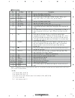
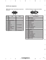
INPUT2 (DVI female connector) pin allocation.
1
8
24
17
9
16
Signal Assignment
1
2
3
4
5
6
7
8
9
10
11
12
13
14
15
16
17
18
19
20
21
22
23
24
T.M.D.S. Data2–
T.M.D.S. Data2+
T.M.D.S. Data2/4 Shield
NC (No connection)
NC (No connection)
DDC Clock
DDC Data
NC (No connection)
T.M.D.S. Data1–
T.M.D.S. Data1+
T.M.D.S. Data1/3 Shield
NC (No connection)
NC (No connection)
+5V Power
GND
Hot Plug Detect
T.M.D.S. Data0 –
T.M.D.S. Data0 +
T.M.D.S. Data0/5 Shield
NC (No connection)
NC (No connection)
T.M.D.S. Clock Shield
T.M.D.S. Clock+
T.M.D.S. Clock–
Pin No.
5
1
15 11
6
10
INPUT1/2 pin assignments
INPUT1 (Mini D-sub 15 pin female connector) pin
allocation.
Input
Output
1
2
3
4
5
6
7
8
9
10
11
12
13
14
15
R
G
B
NC (No connection)
GND
GND
GND
GND
DDC + 5V
GND
NC (No connection)
DDC SDA
HD or H/V SYNC
VD
DDC SCL
+
+
+
+
+
+
+
+
NC (No connection)
+
+
NC (No connection)
+
+
NC (No connection)
Pin No.
Summary of Contents for PDP-42MXE10
Page 9: ...PDP 425CMX 9 5 6 7 8 5 6 7 8 C D F A B E ...
Page 27: ...PDP 425CMX 27 5 6 7 8 5 6 7 8 C D F A B E ...
Page 37: ...PDP 425CMX 37 5 6 7 8 5 6 7 8 C D F A B E ...
Page 129: ...PDP 425CMX 129 5 6 7 8 5 6 7 8 C D F A B E ...
Page 132: ...PDP 425CMX 132 1 2 3 4 1 2 3 4 C D F A B E MAIN PWB CONNECTOR WAVE FORM POINT SIDE B ...

