134
PDP-503CMX, PDP-503MXE, PDA-5002
Number
of
Blinks
P.D. Point in
Operation
Error Pont
Possible Part of Error
Circuit State
Operation
P.D. Circuit
Diagnosis Condition
1
Y
DRIVE
IC22
0
6, IC22
14
(Pulse module), IC22
03, IC22
0
4
,
IC22
12, IC22
13, IC22
13, IC22
17, R22
0
9
K22
11
Lo
VCP OCP
2
Y
DC DC
VOFS D/D CONV. BLOCK (Y DRIVE Assy)
IC2
7
02, IC2
7
0
9, IC2
7
15
K
2
7
12
Lo
VOFS OVP
VOFS D/D CONV. BLOCK (Y DRIVE Assy)
IC2
7
0
1,
IC2
7
02, IC2
7
0
9, IC2
7
15
K
2709
L
o
VOFS UVP
Drive section (control signal, output elements etc.) in
normal operation
Q22
11
, Q22
12, R22
7
7, IC22
0
8, IC22
10
VOFS D/D CONV. BLOCK in normal operation
VH D/D CONV. BLOCK (Y DRIVE Assy)
IC2
7
12, IC2
7
16
K
2
7
19
Lo
VH OVP
VH D/D CONV. BLOCK (Y DRIVE Assy)
IC2
7
11
, IC2
7
12, IC2
7
16
K2
7
18 Lo
VH UVP
Drive section (control signal, output elements etc.) in
normal operation
SCAN (A), (B) Assy
SCAN IC
VH D/D CONV. BLOCK in normal operation
IC
5V D/D CONV. BLOCK (Y DRIVE Assy)
IC2
7
0
4, IC2
7
0
6, IC2
7
17
SCAN Assy in normal operation
SCAN (A), (B) Assy
Y DRIVE Assy
SCAN IC
K2
7
13 Lo
IC
5V UVP
IC
5V D/D CONV. BLOCK in normal operation
IC
5V D/D CONV. BLOCK (Y DRIVE Assy)
IC2
7
0
4, IC2
7
0
6, IC2
7
17
SCAN Assy in normal operation
3
X
DC DC
VRN D/D CONV. BLOCK (X DRIVE Assy)
IC3
7
02, IC3
7
12
K
3708
L
o
VRN OVP
VRN D/D CONV. BLOCK (X DRIVE Assy)
IC3
7
0
1,
IC3
7
02, IC3
7
12
K
3705
L
o
VRN UVP
Drive section (control signal, output elements etc.) in
normal operation
X DRIVE Assy
Q3
12
2
VRN D/D CONV. BLOCK in normal operation
4
X
DRIVE
X DRIVE Assy
IC32
0
0, IC32
0
1 (pulse module), IC3
103, IC3
10
4,
IC3
10
6, IC3
10
7, IC3
11
0, IC3
11
3, R3
10
9
K3
103 Lo
VCP OCP
Q3
12
2
K
3
102 Lo
VRN OCP
5
PS
X DRIVE Assy
IC32
0
0, IC32
0
1 (Pulse module)
When P4 connector disconnected, P.D. does not occur
Y DRIVE Assy
IC22
0
6, IC22
14
(Pulse module)
When P3 connector disconnected, P.D. does not occur
MX AUDIO Assy
IC
8
6
0
1 (Audio IC)
When P6 connector disconnected, P.D. does not occur
When pin 5 of P2 connector disconnected, P.D. does
not occur
SW POWER SUPPLY Module
SW POWER SUPPLY Module
When the voltage is not output even if P4, P3 and P6
connectors disconnected
6
ADR
ADDRESS CONNECT A~D Assy
ADDRESS CONNECT A - D Assy,
RESONANCE Assy,
D/D CONV. BLOCK (DIGITAL VIDEO Assy)
Disconnect D8 - D15 connectors
7
ADR K
RESONANCE Assy
TCP damage of IC6704 (ICP), disconnect D16 and
D17 connectors, panel microcomputer is defective,
outside Flash ROM of the panel microcomputer is
defective.
8
DIGITAL
DC DC
D/D CONV. BLOCK (DIGITAL VIDEO Assy)
IC1901
K1
9
0
1 L
o
5.
0V OVP
ADR. PD
ADR. K. PD
K
19
02 Lo
5.
0V UVP
D/D CONV. BLOCK (DIGITAL VIDEO Assy)
IC1901
K
19
03 Lo
3.3V OVP
K
19
0
4
Lo
3.3V UVP
D/D CONV. BLOCK (DIGITAL VIDEO Assy)
IC1901
K
19
0
5
Lo
2.
5V OVP
K
19
0
6
Lo
2.
5V UVP
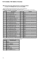
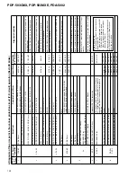
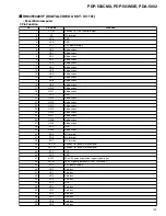
Diagnosis of the error point in the various protection circuit (P.D. circuit) operation (Red LED blinks)
Note: About PS PD
The condition that Red LED blinks five times
(power supply PD)
1
When the internal protection circuit of SW
POWER SUPPLY Module worked
2
When a microcomputer was not able to
identify the PD point
↓
Being careful because the protection circuit
of SW POWER SUPPLY Module cannot
conclude that worked.
Summary of Contents for PDA-5002
Page 5: ...5 PDP 503CMX PDP 503MXE PDA 5002 ...
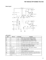
Page 143: ...PDP 503CMX PDP 503MXE PDA 5002 143 Block Diagram Pin Function ...
Page 166: ...PDP 503CMX PDP 503MXE PDA 5002 166 Pin Assignment Top View CXA3516R RGB ASSY IC4603 AD PLL IC ...
Page 167: ...PDP 503CMX PDP 503MXE PDA 5002 167 Block Diagram ...
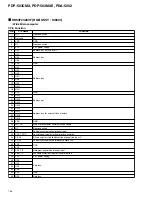
Page 168: ...PDP 503CMX PDP 503MXE PDA 5002 168 Pin Function ...
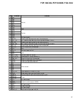
Page 169: ...PDP 503CMX PDP 503MXE PDA 5002 169 ...


